RVO, RVK, RVR, RVP, RV, RVZ, RVF, RVFZ, RLND, RLNDS, RLK
They are used to create a visible break in the power line, separating equipment that is out of service from live parts that are energized. This is necessary, for example, when taking equipment out for repairs in order to carry out work safely. Disconnectors do not have arc extinguishing devices and therefore are intended primarily for switching on and off electrical circuits under voltage or without voltage. Devices are distinguished by:
- type of installation: - for indoor installation - for outdoor installation
- voltage (6, 10 kV)
- current (400, 630A and more)
- execution: - single-pole; - three-pole; - three-pole with grounding blades
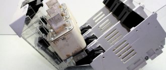
For indoor installation
ARE USED:
- in order to visualize the connection and disconnection, and the actual break of previously de-energized sections of the electrical circuit, for the safe repair of equipment built into the power transmission line network;
- to break electrical circuits operating under low voltage, where the possibility of a discharge arc between the contact knives is excluded;
- for grounding previously disconnected areas when using stationary grounding conductors.
The devices are designed to operate in alternating current networks with a frequency of 50 and 60 Hz and voltages of 6 and 10 kV.
SINGLE-POLE - type RVO, RVK, RVR, RVP R
— disconnector;
B
- for indoor installation;
O
- single-pole;
P
- vertical chopping type;
K
- box-section current-carrying system;
P
- translational movement of the main knives. Available for currents up to 600 A. The numbers in the name mean voltage (kV) and current (A). The knife rotates through an angle of up to 100 and is held in the off position only by its own weight. The angle of rotation of the knife is fixed by a limiter. For the same series at 1000 A, in order to reduce the effort of pulling out the knife, an intermediate shaft was introduced.
| Single pole | ||||||
| Brand | Durability, kA | Dimensions, mm | Weight, kg | |||
| Electrodynamic (amplitude) | Thermal | Length | Width | Height | ||
| RVO-10/400 | 41 | 16 | 468 | 72 | 156/429 | 5,9 |
| RVO-10/630 | 52 | 20 | 468 | 72 | 160/433 | 6,3 |
| RV O-10/1000 | 100 | 40 | 480 | 92 | 163/440 | 11 |
| RLVOM-10/1000 | 100 | 40 | 486 | 380 | 199/460 | 14…17 |
| RV K-10/2000 | 85 | 31,5 | 560 | 350 | 280/500 | 26 |
| RVR(Z)-10/2500 | 125 | 45 | 1050 | 470 | 318/545 | 65 |
| RVR(Z)-10/4000 | 200 | 71 | 610/1050 | 470 | 318/545 | 65 |
| RVR(3)-20/6300 | 260 | 100 | 910/1400 | 700 | 680/1050 | 222 |
| RVR(3)-20/8000 | 320 | 125 | 1400 | 700 | 680/1050 | 238 |
| RVP(3)-20/12500 | 490 | 180 | 1600 | 820 | 857 | 625 |
| RV K-3 5/2000 | 115 | 45 | 980 | 700 | 550/1010 | 74 |
THREE-POLE - types RV, RVZ, RVF and RVFZ are three current conductors mounted on one frame with a common shaft, rods and drive lever.
RVFZ - symbol: F - figured; Z - with grounding knives.
The conductor consists of two fixed contacts and a movable knife connecting them. The knife is held in the on position by rods and a shaft. By rotating the shaft through a PR-P type drive (front connection) or PR type (10 - rear connection; 11 - front connection), the movable knives are turned on or off. The devices are installed in alternating current networks with a frequency of 50 Hz and voltages of 6 and 10 kV.
| Brand | Variant of arrangement of grounding knives | Option for bushing arrangement | Overall dimensions, mm, no more | Weight, kg, no more | ||
| L | H | B | ||||
| RV 10/1000 U3 | — | I var. – without bushings. | 654 | 199 | 472 | 28 |
| RV 10/630 U3 | 182 | 464 | 25 | |||
| RVZ 10/1000 I U3 | I var. – grounding blades on the side of detachable contacts RVS | I var. – without bushings. | 704 | 197 | 622 | 30 |
| RVZ 10/630 I U3 | 186 | 589 | 28 | |||
| RVZ 10/1000 II U3 | II var. – grounding blades on the side of the hinge contacts | I var. – without bushings. | 197 | 622 | 30 | |
| RVZ 10/630 II U3 | 186 | 589 | 28 | |||
| RVZ 10/1000 III U3 | III var. – grounding blades on both sides | I var. – without bushings. | 744 | 197 | 745 | 33 |
| RVZ 10/630 III U3 | 186 | 713 | 31 | |||
| RVF 10/1000 II U3 | — | II var. – bushings on the side of the hinge contacts. | 722 | 202 | 437 | 34 |
| RVF 10/630 II U3 | 32 | |||||
| RVF 10/1000 III U3 | — | III var. – bushings on the detachable contact side. | 437 | 34 | ||
| RVF 10/630 III U3 | 32 | |||||
| RVF 10/1000 IV U3 | — | IV var. – bushings on both sides | 406 | 39 | ||
| RVF 10/630 IV U3 | 37 | |||||
| R V F Z 10/1000 I-II U3 | I var. – grounding blades on the side of the detachable contacts | II var. – bushings on the side of the hinge contacts. | 199 | 649 | 39 | |
| R V F Z 10/630 I-II U3 | 35 | |||||
| R V F Z 10/1000 II-II U3 | II var. – grounding blades on the side of the hinge contacts | II var. – bushings on the side of the hinge contacts. | 39 | |||
| R V F Z 10/630 II-II U3 | 35 | |||||
Option for the location of grounding knives: I - on the side of the detachable contacts;
II - from the side of the hinge contacts; III - on both sides. Option for arrangement of bushings: II - on the side of the hinge contacts; III - from the side of detachable contacts; IV - on both sides
Installation of disconnectors and drives.
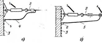
The installation of disconnectors consists of the following operations: inspection, lifting onto supporting structures and fastenings, checking and adjusting the main and signal contacts, checking the mounted disconnector and drive in operation. Before installation, the disconnectors are subject to inspection and revision: check the condition of the porcelain parts, the absence of cracks, chips, damage to the glaze; reinforcement strength; reliability of fastening of all components and parts; serviceability of the contact system; no shells, dents or rust. Detected defects are eliminated by grinding and filing, bolted connections are tightened, rubbing parts are lubricated with a thin layer of technical petroleum jelly, damaged porcelain parts are replaced. Inspection of disconnectors is usually carried out in workshops, outside the installation area. The disconnector is lifted to the installation site and secured to bolts or pins without tightening the nuts to capacity. Depending on the weight, it is lifted by the frame manually using a portable tripod or hoist. Lifting the disconnector by insulators or knives is not allowed. Simultaneously with the installation of the disconnector, the drive is mounted and the transmission between them is assembled. The disconnector and drive are installed so that the axial lines, aligned with level and plumb, do not deviate by more than ± 2 mm. The disconnector and its drive are attached to the wall or structure firmly and reliably. Bolts must be fully threaded; when the nut is tightened, there should be a free end of the bolt with no more than two or three threads. The disconnector and its drive are fastened using a level and plumb line. To adjust their position, sheet steel linings with a hole for the passage of fastening bolts are used. When aligning, make sure that the position of the drive and disconnector shafts is strictly horizontal. When installing several single-pole disconnectors connected into one set, their shafts must be located on the same horizontal axis. After installation and verification of the relative position, the disconnectors and the drives to them are finally secured by tightening the bolts, nuts and locking devices to failure, and the final assembly of the transmission is carried out. To do this, levers are installed on each disconnector and drive disk, forks are screwed onto both ends of the rod, and the rod is secured with pins and cotter pins. In addition, to maintain traction in the event of a breakdown or disengagement, a draft catcher is installed. The transmission parts are connected with conical pins. After carefully checking the alignment and adjusting the lengths of the mating parts, holes are drilled with a cylindrical drill and deployed with a conical reamer for pins of the appropriate size. The movable stop on the drive shaft and the levers on the shafts of the disconnector and drive are pinned in the same way, but before this all work on adjusting the disconnector with the drive must be completed (Fig. 3, a, b).
Rice. 3. Installation of a three-pole disconnector with a PR-10 drive : a - RV, b - RVZ; 1 - auxiliary contacts, 2 - drive, 3 and 4 - plugs, 5 - disconnector
When the transmission axes from the disconnector to the drive are located in different planes, the disconnector shaft is lengthened using a coupling and the connecting shafts are secured with tapered pins. The free end of the shaft is secured in an end or support bearing mounted on the side wall. When constructing a more complex transmission in different planes, not only the shaft is lengthened, but also intermediate bearings are installed, on which the intermediate shafts with levers mounted on them are secured. In this case, the rod is made up of individual elements connected to each other using forks and secured to the corresponding levers with pins and cotter pins. After installing the disconnectors and drives for them, as well as after assembling the transmission, final adjustment of the disconnectors and drives is carried out and the levers are secured on the shafts with thrust screws. When adjusting, observe and fulfill the conditions that ensure normal operation of disconnectors and drives. The knives are positioned coaxially without distortion with respect to the fixed contacts. When turned off, the knife must be in fixed contact. To eliminate shortcomings in the relative position of the knife and the fixed contact, the latter is slightly shifted relative to the insulator on which it is mounted, or the insulator is shifted relative to the frame, or the insulator is rotated around its axis. Once the knife and fixed contact have reached the correct position, tighten all bolted connections. The simultaneous closure of the contacts is checked as follows: slowly bring the gear to switch on until it comes into contact with the moving contact and in this position measure the gaps remaining between the fixed contacts and the knives of the remaining poles. Clearances not exceeding 3 mm for disconnectors up to 10 kV are considered acceptable. With a large difference in timing, adjustment is made by changing the length of the transmission links. By measuring the force of pulling the knife from the fixed contact, check the contact pressure with a dynamometer or spring scales with dry (grease-free) contact surfaces. The angle of rotation of the knives is set by the manufacturer for each type of disconnector. For example, for RV-10/400 the angle between the disconnector's off and on positions is 65°. Permissible deviation from the norm is ±3°. If necessary, it can be adjusted by changing the length of the rod. When adjusting the drive, ensure that the on and off positions of the disconnector and the drive correspond to each other: when the handle of the lever drive is in the upper position, the disconnector must be on, and when it is in the lower position, it must be off. In both extreme positions the drive is locked with a latch. The adjustment is considered complete if the effort of one person’s hand is sufficient to turn the disconnector on and off. The KSA signal contacts are regulated by changing the position of the levers on their shaft and the disconnector drive. They serve to close and open interlock circuits, signal lamp circuits and other auxiliary electrical circuits. These contacts, designed for installation with switches and disconnectors, have (depending on the purpose) from 2 to 12 contacts for connecting circuits. The design of the KSA contacts is simple and easy to install and operate. Their main elements are fixed and rotary contacts, a roller for attaching movable contacts, and a disk for connecting at different angles with the drive lever. The latter is connected at the other end to the drive of the switch or disconnector (for single-pole disconnectors - with a knife). When assembling the KSA, rotary contact washers are placed on the roller so that the contacts for closing and opening alternate. If the diagram requires a different arrangement of rotary contact washers, carry out the corresponding bulkhead of the KSA. The drive lever can be moved to the required position along the entire circumference of the disk, using holes in it and in the lever itself. The main requirement for adjusting the KSA contacts is that the signal to turn off the disconnector begins to operate after the knife of the disconnector has passed 75% of the full stroke, and the signal to turn on - no earlier than the moment the knife touches the fixed contacts. After adjusting the disconnector, the lever is finally secured to its shaft using conical pins with a diameter of 6 mm and a length of 60 mm. Holes are drilled in the lever and shaft, the diameter of which is 0.2-0.3 mm less than the diameter of the pin. Work on installing and adjusting disconnectors is considered complete if the disconnector drive and the entire transmission system operate smoothly, without chafing. The idle speed of the drive handle, resulting from gaps and elastic deformations of the entire transmission system from the drive handle to the knives, should not exceed 5. The drive in extreme positions is automatically locked with special devices. When switched on, the disconnector blades fall into the fixed contacts in the center and enter them without impacts or distortions, not reaching the stop by 3-5 mm. The non-simultaneous switching of the knives of two-pole and three-pole disconnectors should not exceed 3 mm when measuring this distance between the knife and the fixed contact. Surface contacts must have at least three points of contact that do not lie on the same line, and linear contacts must have at least two points of contact. The presence of these areas is checked with a probe 0.05 mm thick and 10 mm wide, which should not pass more than 5 mm inside the surface contact or along the contact line in linear contact. Rigid clamping of the contact springs of the disconnectors is not allowed. When the knife is in the on position, there must be a gap of at least 0.5 mm between the coils of spiral springs or plates of flat springs. The adjusted disconnector is checked by several turns on and off. These operations are performed with one movement of the drive without jerks or impacts in the knives, in compliance with the specified rotation angles of the moving contacts and levers. In extreme positions, the removable pin fixing the position of the drive must fit freely into the hole in the rotating sector and securely lock the drive. Upon completion of installation, before putting into operation, the contact parts of the disconnector are lubricated with technical petroleum jelly, wrapped in paper and secured with twine.
Issues covered
- How are disconnectors arranged and what are they used for?
- How to install, secure and adjust a three-pole disconnector?
- What is the structure of the lever drive and how is the transmission mounted from the drive to the disconnector?
- What are the KSA signal contacts used for and how are they installed?
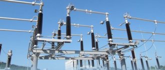
For outdoor installation
External, man-made environmental influences, natural and climatic operating conditions, impose certain requirements on the design of the disconnector.
The main requirements include: the presence of sufficient insulation in a polluted and humid environment, and mechanical strength when contact pairs become icing, often using built-in ice-breaking devices. Explanation of the abbreviation in brand designations:
- D - two-column;
- 3 - with grounding knives;
- L - linear;
- N - outdoor installation;
- O - single-pole;
- R - disconnector.
Outdoor horizontal rotary type disconnectors of the R L N D series are used:
- for the purpose of visualizing connection/disconnection, and the actual rupture of previously de-energized sections of the electrical circuit, for the safety of work in networks of high-voltage power lines;
- to break electrical circuits operating under low voltage, where the possibility of a discharge arc between the contact knives is excluded;
- for grounding previously disconnected areas when using stationary grounding conductors.
For these types, the rated voltage is 10 kV, but if necessary, RLND disconnectors can operate up to 750 kV.
Structurally, the RLND has one or two stationary grounding conductors. The connection between the main and grounding circuits is opened through lamella contacts, the pressure in which is created by springs.
Control is carried out by manual drives type PRN(Z)-10UHL1 or drives type PR-2BUHL1
Characteristics of disconnectors rlnd
| Name and type | Characteristics | |||
| Thermal resistance current, kA | Limit through current, kA | Weight, kg | Accessory drive, type | |
| with a movable contact terminal on a rotary column without grounding conductors | ||||
| R L N D-10B/630 UHL1 | 12,5 | 31,5 | 31 | PRG-2UHL1 |
| R L N D-10B/315N T1 | 10 | 25 | 30 | PRG-2T1 |
| R L N D-10B/630N T1 | 12,5 | 31,5 | 31 | — // — |
| R L N D-10B/400N UHL1 | 10 | 25 | 35 | PRG-2UHL1 |
| R L N D-10.IV/400N UHL1 | 10 | 25 | 28 | — // — |
| with a movable contact terminal on the rotary column and with one grounding switch on the side of the rotary column | ||||
| R L N D.1 -10B/315N T1 | 10 | 25 | 39 | PRG-2BT1 |
| R L N D.1 -10B/630N T1 | 12,5 | 31,5 | 40 | PRG-2BT1 |
| R L N D.1 -10B/400N UHL1 | 10 | 25 | 39 | PRG-2BUHL1 |
| R L N D.1 -10.IV/400N UHL1 | 10 | 25 | 36 | — // — |
| R L N D.1 -10B/630 UHL1 | 12,5 | 31,5 | 40 | — // — |
| with a movable contact terminal on a rotating column and with two grounding switches | ||||
| R L N D.2-10B/400N UHL1 | 10 | 25 | 43 | PRG-2BUHL1 |
| R L N D.2-10. IV/400N UHL1 | 10 | 25 | 40 | — // — |
| R L N D.2-10B/630 UHL1 | 12,5 | 31,5 | 50 | — // — |
Outdoor horizontal-rotating type R L N D-I series are used for:
- visualization of connection and disconnection, and real rupture of previously de-energized sections of the electrical circuit, for the safe repair of equipment built into the power transmission line network;
- breaking electrical circuits operating under low voltage, where the possibility of a discharge arc between the contact knives is excluded;
- grounding of previously disconnected areas when using stationary grounding conductors.
Structurally, the product has one or two stationary grounding conductors.
The connection between the main and grounding circuits is opened through lamella contacts, the pressure in which is created by springs. R L N D-I-10B is made on porcelain insulators, R L N D-I-10.II and R L N D-I-10-.IV are made on polymer insulators (with tracking-erosion-resistant coating) having high discharge characteristics in dirty and wet conditions and mechanical characteristics that ensure reliable operation under seismic impacts up to 9 points on the MSK-64 scale.
RLND-I at 200 A are controlled by a manual drive PRNZ-10UHL1, and at 400 A - by a manual drive type PRNZ-10UHL1 or a block manual drive PR-2BUHL1. The drives have a mechanical interlock between the main knives and the grounding switches.
| Name and type | Characteristics | |||
| Thermal resistance current, kA | Limit through current, kA | Weight, kg | Accessory drive, type | |
| with a fixed contact terminal on a rotating column without grounding conductors | ||||
| R L N D- I-10B/400N UHL1 | 10 | 25 | 33 | PRG-2UHL1 |
| R L N D- I-10.IV/400N UHL1 | 10 | 25 | 23 | — // — |
| R L N D- I-10B/ 200 UHL1 | 6,3 | 15,75 | 30 | PRN-10MU1 |
| R L N D- I-10.IV/ 200 UHL1 | 6,3 | 15,75 | 20 | — // — |
| R L N D- I-10/ 200 UHL1 | 6,3 | 15,75 | 30 | — // — |
| R L N D- I-10/ 400 UHL1 | 10 | 25 | 30 | PRG-2UHL1 |
| with a fixed contact terminal on the rotary column and with one grounding switch on the side of the rotary column | ||||
| R L N D- I.1-10B/400N UHL1 | 10 | 25 | 39 | PRG-2BUHL1 |
| R L N D- I.1-10.IV/400N UHL1 | 10 | 25 | 34 | — // — |
| R L N D- I.1-10B/ 200 UHL1 | 6,3 | 15,75 | 43 | PRN3-10UHL1 |
| R L N D- I.1-10.IV/ 200 UHL1 | 6,3 | 15,75 | 34 | — // — |
| R L N D- I.1-10/ 200 UHL1 | 6,3 | 15,75 | 34 | — // — |
| R L N D- I.1-10/400 UHL1 | 10 | 25 | 39 | PRG-2BUHL1 |
| with a fixed contact terminal on a rotating column and with two grounding switches | ||||
| R L N D- I.2-10B/400N UHL1 | 10 | 25 | 39 | PRG-2BUHL1 |
| R L N D- I.2-10. IV/400N UHL1 | 10 | 25 | 38 | — // — |
| R L N D- I.2-1 0B/200 UHL1 | 6,3 | 15,75 | 43 | PRNZ-10UHL1 |
| R L N D- I.2-1 0. IV/200 UHL1 | 6,3 | 15,75 | 38 | — // — |
| R L N D- I.2-1 0/200 UHL1 | 6,3 | 15,75 | 38 | — // — |
| R L N D- I.2-1 0/400 UHL1 | 10 | 25 | 39 | PRG-2BUHL1 |
Physical characteristics of RLND
RLND is offered in the form of a frame on which a movable or fixed contact system is placed, which is responsible for turning off or turning on the electric current and grounding the contact knives, as well as the manual drive of the PR.
Most often, modern manufacturers of such products install them on poles in front of transformer stations with air input. You can often find them as part of CSR cells.
Before choosing a disconnector, it is very important to pay attention to such important features as the design of its frame and drive. Very often, these elements may be of poor quality, since their production may use low-quality metal with a small thickness, which significantly reduces the operating life of the device. That is why, before purchasing an RLND, you should pay attention to its strength and reliability, because otherwise, this can lead to rapid wear and deformation of the device.
The insulating sphere of the RLND consists of 4-6 special insulating elements, half of which are placed on the levers, and the remaining half on the channels.