Light switches, connection
According to the amount of switched load, switches are divided into:
- single-key;
- two-key;
- three-key, etc.
There are so many keys, so many contact groups inside, so many devices this switch can control. All switches have two positions “On” and “Off”, or “0” and “1”.
According to the installation option, switches are:
- for hidden electrical wiring;
- for open wiring.
By functions performed:
- dimmers;
- checkpoints;
- cross.
We will talk about each of them a little later, in what situations they are used and how they are actually connected. Now let’s decide what we will connect, what chandelier will illuminate your room. What are they, and let's look at the connection options.
Ceiling chandeliers - varieties
According to the number of lampshades, there are:
- chandeliers with one shade or lampshade (single-arm);
- with two shades or lampshades (double-arm);
- three-arm (with three shades), etc.
Basically, the number of lampshades depends on the style of execution (classic, loft, modern, etc.) and design. Moreover, the more shades and lamps on a chandelier, the greater the lighting power and, as a rule, the greater power consumption of electricity. The larger the area a given lighting device can illuminate.
By type of control, chandeliers are divided:
- wired control (two or three wire connection, plus a grounding contact if the chandelier has a metal structure);
- wireless control (via radio or from a phone via Bluetooth);
- combined options.
If you haven't bought a chandelier yet, just plan to do so. In this case, it will be very important to determine what type of wiring is installed in your apartment or house. The choice of a chandelier with a suitable connection diagram and control option depends on this.
12 connection diagram options
Below is a table to help you make this choice. It is enough to determine what type of wiring you have and what switch is installed. If you select the right chandelier, no major alterations or interventions will be required in your existing wiring diagram. With the exception of some options, where there is a “change required” mark. We will discuss these changes below when we take a closer look at connecting the chandeliers of these models.
Note. The table shows the most common connection options; in fact, there are many more of them!
To decide on the choice of chandelier and connection option
- You need to determine your wiring type (2, 3 or 4 wire). Just look at the ceiling and see how many wires you have coming out of the ceiling in the place where the chandelier is attached.
- Which switch is used to control the lighting (in table 1, 2-key or dimmer).
- We select from the table the desired functions that correspond to the option number of your electrical wiring.
- And next to it, in the column, we see which chandelier performs these tasks.
You need to pay attention!
If you have 3 wires coming out of the ceiling, then in this case your wiring may have 2 “scenarios”. The difference will be that according to one option, one “phase” will come from the switch to the chandelier, and in the other option there will be two – “L1” and “L2” (pay attention to the number of keys on your switch).
If your wiring has 4 wires, then you can use any type of chandeliers and any controls here.
Connection options
Connecting a chandelier and other lighting devices is done by crimping, soldering or using terminal adapters.
The first option involves connecting the conductor cores by crimping them with a fixing sleeve. The entire procedure is carried out with a special tool - press tongs. This method complies with all regulatory documents.
The second method is considered one of the most reliable, but difficult to reproduce. It is practically not used due to the inconvenience of working at height.
When choosing one of the methods for contacting conductors, you must remember that aluminum under constant load acquires plasticity. Connections of this type require regular inspection. You also need to periodically tighten the fixing bolts.
You cannot twist aluminum and copper wires together - a galvanic pair is formed, which, even with a slight increase in the level of humidity in the apartment, can reproduce an electrochemical reaction in the form of oxidation.
This process breaks the contacts, and the junction begins to heat up. It is for this reason that fires occur.
If you use terminals to connect, you will need to remove 9-11 mm of insulating material from the conductors. For this purpose, there are special marks on the clamps that determine the required level of stripping.
The use of terminal blocks is considered relevant. At the moment, the model range of this connecting element is quite wide - from the classic screw version to the spring modification.
Primary requirements
The most important requirements when working with electrical wiring are compliance with safety rules and rules for installing electrical devices. There is no point in studying the “bible” of electricians: “Rules for the safe operation of consumer electrical installations” (RBEEP) and “Rules for the construction of electrical installations” (RUE). Such documentation is necessary mainly for those people for whom working with electricity is their main activity. For home repairs, to connect a chandelier with a switch, it is enough to know and follow simple rules.
- Rule 1. All tools that will be used to perform work on electrical wiring must have high-quality insulation of the handles.
Tool set with insulated handles
- Rule 2. Most work should be performed only on de-energized wires. It is not enough to flip the light switch. To completely cut off the power, there is a main switch on the apartment panel, which must be turned off before starting work.
- Rule 3. The light switch is mounted exclusively in the break of the phase wire.
Correct connection of the switch
The switch is mounted in the phase wire gap
Wiring diagram for a chandelier with a double switch
As can be seen from the figure, there are three wires suitable for the double switch, one of which comes from the junction box, and the other two are used to connect the lamp. Therefore, when installing new wiring, you need to use a cable with 3 wires.
Connecting a chandelier to a double switch follows the same rules as connecting a regular lamp.
What are the risks of polarity reversal?
Quite often you can hear from non-professional advisers that the switch can be installed on any wire. Like, what difference does it make, because when the contacts are open, no current flows through the lamp and that’s enough. This is wrong.
The fact is that if the switch breaks the neutral conductor, then no current will flow through the chandelier lamps, but there will be a phase potential on all wires, which threatens an electric shock during work.
A less dangerous, but unpleasant feature of such switching is that fluorescent lamps and “housekeeper” lamps can glow faintly or flicker even in the off position.
Tool
To connect a chandelier or other lamp you will need the following:
- Straight and Phillips screwdrivers;
- Side cutters;
- Pliers;
- Sharp knife;
- Measuring instrument, digital or pointer;
- Indicator screwdriver (probe);
- Insulating tape.
The purpose of most tools is clear without comment. Why do you need a knife? In some cases, namely when removing insulation from single-core conductors of an electric cable, side cutters or pliers cannot be used, since a transverse cut of the core on the connected wire will lead to its fracture. This is especially true for aluminum wires.
The insulation must be cut with a sharp knife, similar to how a pencil is sharpened. Longitudinal scratches on wire strands are not dangerous.
The indicator screwdriver is used to search for the phase conductor. And although its end provides the possibility of using it as a screwdriver, this is not necessary, since the mechanical strength of the indicator is very low and it is almost impossible to tighten the screw normally without breaking the tool (it is possible, but the tool will not last long).
Indicator screwdriver - the main tool of an electrician
You should dwell in more detail on measuring instruments. They are digital and pointer. For most parameters, digital is preferable. They have high accuracy, are not afraid of shocks and falls from a height, and are protected from overload.
The pointer device should be used only in the position for which it is intended (most portable devices should be placed horizontally); a fall from a height will with a 100% probability disable it, as will overload if the regulator is incorrectly set. The undoubted advantage of a pointer device is that voltage measurements can be made without a built-in power source.
Inexpensive pointer and digital testers made in China
Note for all types of devices: the operating range must provide for measuring an alternating voltage of at least 500 V.
Wire marking
There is no single international standard regarding color marking. The exception is the grounding cable, which is painted yellow-green and has the Latin designation “PE”. Depending on the country of origin, the markings of the remaining wires may differ. Most often, the phase is designated by the letter “L”, and the zero or working contact – “N”.
You can locate the required cable using different types of measuring instruments or a voltage indicator screwdriver.
Step-by-step installation instructions
Conventionally, connecting a switching device can be divided into several stages. They start with the cables: if the wiring is old, then it definitely requires replacement.
Then you need to correctly connect the wires in the junction box, and finally in the switch mechanism. To install a chandelier or lamp, you usually use the instructions provided by the manufacturer.
Stage #1 – preparing the walls
It is recommended to skip the wall gating stage only if new wiring with copper conductors of a suitable cross-section has already been laid. When in doubt, it is best to consult an electrician.
For the lighting group, a regular VVGng wire with a cross section of 1.5 mm² is suitable. If sockets are connected along with lighting, then it is better to immediately take the same wire, but 2.5 mm².
The preparation of the walls includes gating, arrangement of installation sites for socket boxes and distribution boxes. At the same stage, you can install an additional circuit breaker in the electrical panel.
A separate protective device will come in handy when the lighting line requires repair - only one circuit can be turned off, the rest will work as usual.
The grooves are knocked out with a hammer drill, a circular saw, or even manually, but to cut even grooves, a special tool is used - a wall chaser equipped with a vacuum cleaner
The lighting system of a wooden house differs in the type of wiring. The hidden method is not used, since it is extremely fire hazardous and requires maximum cable insulation.
The wires are mounted from the outside on special insulators. Instead of internal switches, overhead switches are installed, but the principle of connecting the cores to the terminals does not change.
After gating of concrete, brick, and aerated concrete walls, the grooves in which the wires are laid are sealed with mortar or alabaster. Then you can plaster and decorate the walls, but it is better to save the location of the wires in a drawing or diagram - until the next repair.
Stage #2 – connection in the distribution box
The distribution box is the chamber where the wiring and connection of the wires takes place. When installing switches or sockets of different types, the connection diagram changes.
But first you need to choose the right junction box. Previously, metal products were used, but now they produce safer and easier-to-install plastic analogues.
There are internal and external models, but it is always easier and more efficient to work with external ones. If you need to urgently disconnect the wires due to replacing the electrical installation, then to access the built-in junction box you will have to dismantle the plaster and then make repairs.
The body of the external model is always visible: just unscrew the cover and perform the necessary actions.
The connection diagram of the cores is simple: the neutral wire from the panel is twisted with the zeros of the two connected lamps, and the phase is sent to the switch. Two output phases from the switch go to the lamps - one for each
If the wire is three-core – and now this is what is most often used – then in the junction box, similar to the neutral conductor, the “ground” is twisted. And if the wiring is old, but reliable, then there is no point in changing it, and you need to use the connection indicated in the schematic image.
There are several ways to connect wires. The most common are twisting followed by insulation and the use of terminals.
Soldering is used extremely rarely. If you are used to using terminal blocks, then you can consider the option of a distribution box with pre-installed terminals.
Stage #3 – installation of lamps
How to install a chandelier with two lamps or two separate lamps depends on many factors:
- lighting fixture models;
- wiring readiness;
- basics for installation.
The easiest way to change lighting equipment is when the wire is routed out at the installation location, for example, in the center of the room.
To install a chandelier, you need to perform two operations: hang the lighting fixture on a hook or bracket and connect the wires correctly
If the ceiling is new and is a suspended structure (tension, plastic or plasterboard), then additional fasteners or mortgages should be installed to install the chandelier.
When two phase wires are supplied from a two-key switch to the lamp, they are connected alternately - each to its own lamp. Also, two neutral wires are pulled from the distribution box - they are also scattered among different lamps.
If both bulbs are connected to the same wire, they will turn on/off at the same time, and there is no point in installing a double switch.
When installing two separate lamps in different rooms, the connection principle remains the same, only the routing of the wires from the junction box changes - they are directed in different directions. As a rule, the rooms are located next door. It is better to mount the distribution box above the switch, approximately 15-20 cm from the ceiling.
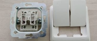
Stage #4 - installation of the switch
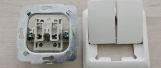
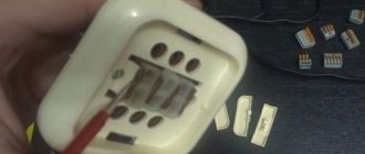
There are no difficulties in either installation or connecting the two-keyboard. It is installed in a socket box or directly into the wall, secured with claws or a screw connection. Exactly how the wires are connected is shown in the photo.
The double switch is always connected only to the phase conductor coming from the distribution box, where it comes from the electrical panel. The core is inserted into the terminal marked “phase L”. From the output contacts L1 and L2, the phase conductors go to the lamps (+)
If the chandelier has not two, but more lamps, which is much more common, then the connection is made in groups. All lamps are divided into two equal or unequal groups, and then the wire from contact L1 is directed to one, and the wire from contact L2 to the second.
Conditional division into groups is made depending on the desired degree of illumination of the room. If you need two intensity modes, weak and bright, then you can connect the first core to one lamp, and the second to the rest. To reach the maximum brightness level, just press both keys.
Wiring continuity
It is not possible to identify a grounded wire in every home. In old buildings they are usually absent. The remaining contacts are also not always marked. To figure out where the “phase” is and where the “zero” is, it is necessary to carry out a dialing.
So, with a two-key switch device, you may need to connect a chandelier with three wires, two of which will be phase, and one will be neutral. To determine the voltage, you need an indicator screwdriver, a tester (multimeter) or a voltmeter.
During the call, the switch key must be in the “ON” position; accordingly, the electricity in the room must also be connected. Upon completion of the work, it is necessary to switch the key to the “OFF” state and turn off the machine on the control panel or unscrew the plugs.
Voltmeter
One of the measuring instruments often used by craftsmen to determine voltage is a voltmeter. Its main advantage is its ease of operation, as well as the absence of the need for an additional power supply (batteries). When working with it, you must remember that its operation must be carried out parallel to the source of electricity and it must be in a strictly horizontal position.
Determining contact voltage using a voltmeter is a simple task. It is enough to fasten the probe wires to the contacts and track the position of the arrow on the indicator. If the value does not change (is at zero), then both wires are phase, and the remaining wire is zero. Then you should move one of the probes to “0”, and the second one in turn to each of the “phases”. The arrow on the device should indicate a value of 220 V. To facilitate further work, it is necessary to mark each wire with a colored marker or Latin letters, where “N” is the neutral contact, and “L” is the phase contact.
When working with a voltmeter, you must adhere to a number of rules:
- during the measurement process, hold the device box only horizontally;
- correctly select a voltmeter for the section of the circuit being measured (do not use weak equipment to measure significant quantities);
- observe polarity.
One of the advanced types of voltmeter is a multimeter or tester. It has a large measurement range and can detect not only voltage, but also resistance, current, inductance, temperature and frequency.
This digital device is more accurate, equipped with overload protection, and, in most cases, a shockproof mechanism. Among the disadvantages, it is worth noting the cost and the need for additional power sources (batteries).
indicator
A passive indicator screwdriver is found in almost every home. Working with it is simple and convenient. It is enough to touch its sting to the bare contact, and it will immediately become clear whether it is “phase” or “zero”. When you touch a phase wire, the indicator on the handle will light up, in other cases it will not.
All work on the wiring and marking of conductors must be carried out with the machine switched on on the panel. Once the process is complete, it is advisable to cut it down.
Why is polarity reversal dangerous?
Polarity reversal is the procedure of applying voltage of reverse polarity to conductors. If connected incorrectly, this phenomenon rarely leads to failure of the device. However, the service life of the lighting fixture is significantly reduced.
In addition, when the chandelier is turned off, despite the absence of current in it, the phase potential in the contacts will be maintained, and this is a direct threat of electric shock during the work.
The second “feature” of polarity reversal is the ability of fluorescent lamps to flicker even when turned off.
Rules for connecting wires
There are no small details when working with electricity. Therefore, we connect the wires in the chandelier according to all the rules. When combined into one group, it is not enough to simply twist them and screw on the protective cap.
You need to connect the wires from the chandelier and the switch in the terminal box
Such twist will sooner or later oxidize and begin to heat up. It is highly advisable to solder such connections. If you know how to handle a soldering iron and tin, definitely do this. This will guarantee normal contact and the connection will not heat up.
Now let's talk about how to connect the wires from the chandelier with the wires from the switch (which are on the ceiling). According to the latest rules, twists are not allowed. Terminal boxes must be used. Most modern chandeliers are equipped with them. If not, buy it at any hardware store or retailer of lighting fixtures.
When using such a terminal box, a problem arises: a twist of a large number of wires simply does not fit into the hole. Output: solder a conductor to the connection (copper, single-core or stranded, with a cross-section of at least 0.5 mm2). This connection is well insulated, and the free end of the soldered conductor is inserted into the terminal box (a long one is not needed - 10 cm is more than enough).
Having inserted all the wires from the chandelier into the terminal block and tightened the screws, the entire structure is raised to the ceiling. There it is pre-fixed, after which the wires are connected to the terminal block in the required order. In this case, it is important to set “zeros” one opposite the other. Phases are connected to phases in random order.
Safety first
Work with electrical wiring must be carried out in compliance with safety precautions and following a clear sequence of actions.
First of all, the rules concern de-energizing the wiring during the process of fitting and stripping wires, installing the operating mechanism of the switch, connecting conductors to terminals and other actions.
The main aspect that you should pay attention to when performing home electrical work is contact with exposed wires. All actions must be performed after turning off the general switch and using special tools
However, to determine the required wire, you will still need a power supply, so you must be as careful as possible in your work and perform all actions only with special tools with high-quality insulation of the handles.
The figure shows that 3 conductors are suitable for the double switch, one of them is directed from the distributor, and the rest are used for contact with the chandelier. The electrical wiring is aluminum and is represented by a three-core wire
Installation of a double switch is carried out only in the phase conductor gap.
When inspecting the completed circuit, it is allowed to turn on and off the lighting fixtures only after complete isolation of the exposed conductors and their final fastening.
Connecting a 3 or 4 wire chandelier to a double switch
When we have decided on the purpose of each wire coming from the switch, it will not be difficult for us to make a connection with the wires on the chandelier. You just need to understand that the chandelier in this case must be assembled according to a certain pattern. Namely, to have 2 groups of lamps, and each to have its own outlet (conductor for connecting to the phase wires from the switch “L1”, “L2”).
Typically, such chandeliers have 3 or more shades. Sometimes alterations are required to change the number and location of lamps in groups that will light up when the corresponding switch keys are turned on. I don’t see any point in dwelling on this in detail, since the assembly of a chandelier with three lamps has already been described above.
This version of lighting fixtures usually has 3 wires for connection, but there are also four wires:
- “L1” - “phase” from key 1
- “L2” - “phase” from key 2;
- “N” - zero contact (common);
- “PE” - contact for grounding connection ( may be absent )
Both options have the same connection diagram. The wires must be connected in accordance with the markings on the chandelier itself.
If your chandelier has 3 wires and the wiring has 4, in this case the wire marked “ground” will not be used. It must be insulated and carefully laid together with other wires.
If, on the contrary, the chandelier has 4 wires, and the wiring is 3-wire, we connect all the wires according to the diagram. And the grounding wire or contact of the chandelier will not be used.
How to connect a chandelier to a two-key switch
Having the desire or if necessary, owners are faced with replacing lighting fixtures. However, when changing the lamp, the switch is left the same. There is a connection problem. There are varying numbers of wires sticking out of the ceiling that need to be connected to the lighting fixture. Before you figure out how to connect a chandelier to a two-key switch, you need to decide how many light bulbs it will have.
How to convert a chandelier designed for a single switch into a double switch
If your chandelier is designed for a single switch, that is, only two wires come out of the base of the chandelier, and there are several lamps, and your electrical wiring allows it, you can try to convert the chandelier to a double switch. The process is labor-intensive, but the result is worth it.
In a chandelier of this design, all wiring from the lamps (shades) comes into one combination of phase and neutral wires. You need to find this place and divide the lampshades into two sections, each of which will be turned on by the corresponding switch key.
After we have found the connection point, do the following:
- The neutral wires remain connected to each other and do not need to be touched.
- We divide the phase wires into two groups of wires instead of one. The division scheme is at your discretion, depending on the number of shades and your personal preferences.
- Connect the common (neutral) wire with the neutral wire coming from the junction box.
- To connect the phase wires from the resulting sections of the lampshades of the sections, you need to run another additional wire from the chandelier to the place where the chandelier is connected to the electrical wiring from the double switch.
Thus, it is quite easy to transform an ordinary chandelier into a three-mode one.
How to decide on a connection diagram for several light bulbs
There is a difference when connecting devices to a 1-key and 2-key switch. For a clearer understanding, let's look at the connection diagrams separately.
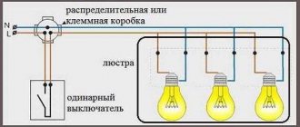
Connect several light bulbs
1. The phase should be led from the meter to the switch, and from the switch to the light bulb; 2. Zero goes directly to the light bulb, bypassing the switch.
This principle is the most common and does not require any additional costs if you need to connect, for example, a chandelier. If you use several light bulbs at once, then with this connection they will light up and go out simultaneously.
Option with wiring connected to a two-key switch
1. The zero goes directly to the light sources, connected in parallel between them; 2. The phase wire goes to the switch, in which each key will supply electricity to separate power plants.
Thus, you can use either two or one light source at once by turning on one or two keys, respectively.
The advantage of this connection is that in the case of different rooms, it is possible to control the light from one switch. And if there is light in one, it’s easy to change the brightness of the light.
In modern houses, when installing electrical wiring, a three-core wire is used. The overall connection picture does not change; only an element is added that “grounds” the wiring. It connects to the metal parts of the lamps, bypassing the switches.
If there is a socket in the node with the switch, then the connection is made differently. The ground wire must be run from the junction box to the outlet due to the higher potential load on the outlet than on the light bulb.
The most common mistakes in connecting a chandelier
Errors during installation and connection occur not only among novice electricians; even among experienced specialists, it often happens that the chandelier does not shine at all the way it should. These mistakes are typical and banal.
If the number of wires in the chandelier and on the ceiling do not match
It may turn out that the chandelier you purchased has three wires, but there are only two wires on the ceiling where the chandelier is mounted, and the switch, accordingly, is single. Or vice versa. The algorithm for connecting a three-arm chandelier to a single switch looks like this:
- Connect the neutral wire of the chandelier to the neutral wire on the ceiling.
- In the terminal block of the chandelier, install a jumper between the phase wires or clamp them in one terminal and connect them to the phase wire on the ceiling.
With this connection scheme, it will no longer be possible to regulate the light level.
In the opposite situation, when the home electrical wiring has three wires (two phase and one neutral) and a double switch, and the chandelier has only two wires, the connection is made in the following sequence:
- Using a voltage indicator, you need to determine the neutral wire and connect it to any of the wires on the chandelier.
- Clamp the other two wires (phase) into one terminal, or install a jumper.
ATTENTION: In such a situation, you should definitely check all three wires with an indicator so as not to accidentally short-circuit the network if the third wire is not phase, but neutral. This, unfortunately, also happens.
Incorrect connection of double switch
This is the most common mistake, which consists in connecting the incoming phase wire to one of the output contacts of the switch. With such a connection scheme, the chandelier cannot function normally, since one section of the lamps turns on only if voltage is applied to the other section.
That is, if the incoming phase is connected to the left contact of the switch, when the left key is pressed, the phase enters the distribution box through the lower input contact and turns on one section of the lamps. The next time you press the right key, another section is turned on. But when you open the left key, all sections are turned off.
When the left key is pressed, it is impossible to turn on the right key.
The reason for the dependence of the right key on the left is that initially the phase entered through the input contact of the left key switch, and the left key, when turned off, breaks the phase in both sections at once.
To eliminate this error, you should swap the connections of the incoming and outgoing phases of the switch.
Instead of a phase wire, a neutral wire passes through the switch
According to the rules of electrical installations, there is a procedure for connecting a switch that closes and opens the circuit by breaking the phase. How does it look on the diagram? The neutral wire, bypassing the switch, is laid from the distribution box directly to the neutral wire of the ceiling lamp. The phase wire from the junction box passes through the switch key, which breaks the circuit.
However, in practice, sometimes an incorrect connection occurs: it is not the phase wire that passes through the switch, but the neutral wire. That is, when the switch key is turned off, the electrical wiring remains energized, despite the fact that the lighting is not on. This is fraught with the possibility of electric shock when replacing a lamp, if you accidentally touch the exposed parts of the chandelier shade, or if the insulation of the wire is broken.
Therefore, if possible, it is advisable to eliminate such a connection error.
This violation of the connection diagram can be detected using a voltage indicator, which, when the switch is in the “off” state, shows the presence of a phase on the ceiling wires.
Incorrect connection diagram for the neutral wire of the chandelier
This error is the reason that only part of the light bulbs in the chandelier turn on normally, the rest either shine weakly or do not turn on at all. As previously discussed, if there are three wires, the phase wires are each connected to a separate section of light bulbs, while the neutral wire is common to all light bulbs, which are all connected to it in parallel.
If you mix up the wires and connect the interconnected light bulbs, say, of the first section to zero instead of the phase, and connect all the light bulbs of both sections to the phase (instead of zero), then when you press the first key in the first section, the light bulbs will turn on, since they go there at the same time both zero and phase.
When you press the second key in the second section, the light bulbs will not light, since both incoming wires will be phase, and in order for the light bulb to shine, a phase with zero must be supplied to it at the same time.
Design and principle of operation
With the help of such switches, it is possible to control the same light source from two or more points, turning it on in one place and turning it off in another (or vice versa). Thanks to this, while moving, the corridor will be constantly illuminated along the entire path.
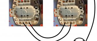
The rear view of two-key pass-through switches from different manufacturers is shown in the figure below.
The connection diagram for a double pass-through switch can be implemented using a single-key device, so the question is quite logical: what is the second key for then?
To answer this you will need to understand the following explanations:
- A two-key pass-through switch also contains changeover contacts, but in this case the number of switching groups of lamps increases from one to two .
- The number of conductors connecting two spatially separated switching devices increases to 4.
- With this connection diagram for two-key pass-through switches, it becomes possible to switch two lighting bulbs at once (one to turn on and the other to turn off).
- To see the difference between two-key and single-key switches, a direct comparison will help us. To do this, you will need to remember the connection diagram for the pass-through switch, in which the connection is made on only two wires.
Important! When examining the two schemes together, one can immediately see the difference not only in the number of connectors, but also in the functionality of the devices used.
If in the case of a single key only one group was switched (the lamp was turned on and off), then in a chain with a two-key switch there are already two such groups. According to the diagram of two-key pass-through devices, in this situation it will be possible to turn on the first of 2 light bulbs while simultaneously turning off the second and vice versa.
Compliance with safety rules when connecting a chandelier
Working with live parts always involves a certain amount of risk. Connecting a chandelier to a home is no exception, and the work is done at height. To protect yourself and others during electrical installation work, you must follow the following safety rules:
- Carefully study the instructions for connecting the chandelier.
- The power tools used in the work must be in good working order, especially with regard to the insulating parts of the tools.
- Equipment for climbing to heights - stepladders and other devices - check for reliability and stability of the structure.
- Before starting work, stop the power supply by turning off the circuit breakers in the electrical panel.
Sources
- https://600doneba.ru/kak-podklyuchit-lyustru/
- https://LampaGid.ru/osveshchenie/kvartira-i-ofis/podklyuchenie-lyustry
- https://svetilnik.info/lyustry/podklyuchenie-lyustry-k-dvojnomu-vyklyuchatelyu.html
- https://kak-sdelano.ru/elektrica/podklyuchenie-lyustryi
- https://otlichnyjremont.ru/elektrika/sekrety-i-tonkosti-raboty-po-podklyucheniyu-lyustry-k-vyklyuchatelyu.html
[collapse]