“Grandma, please give me that wire,” one electrician asked an old woman passing by. And a minute later he said to his partner: “You see, Misha. You claimed that there was a phase here, but it turned out to be zero.”
Such an anecdote with a beard very clearly reveals the ideology of checking voltage in home wiring, and not only in it.
Peculiarities
The device in question combines several devices that connect differently to one section of the circuit.
In order to use it correctly and get a complete picture of the state of the electrical network or an individual outlet, you should know at least some theory. At a minimum, you should understand how you can measure voltage, and how exactly you can measure current, and how you can correctly connect this or that device. When the cables are connected to a working power source, they receive an electrical voltage measured between zero and phase. To put it simply, it’s “– + “and” – “. The voltage in a standard electrical network can be measured both without a load connected to the electrical network and with it present.
There may also be a ground connection in the outlet.
But the current itself appears only when the circuit is closed. Only after this does it begin to strive to move between the poles. In this case, measurements should be carried out exclusively when the device is connected in series. To measure the magnitude of the current, you should first let it pass through the multimeter.
To ensure that the multimeter itself does not distort the current strength and displays the most accurate data, its resistance should be kept to a minimum. If it is set to the current measurement mode, and at the same time you try to measure the voltage with it, then the result will be a simple short circuit. Although modern models do not have this problem, and voltage and current measurements are made using the same terminal connection. But it won’t hurt to remember some knowledge from the physics course. According to them, the same voltage will be observed in sections of the electrical circuit connected in parallel, and the current strength will be the same only when the conductor connection is in series.
In order to avoid errors and inaccuracies, before starting measurements, you should analyze the markings on the contacts of the multimeter and the mode switch. Note that in domestic conditions several groups of electrical networks are used . The most commonly used system in modern homes is a system with a voltage of 220 volts at a frequency of 50 hertz. Usually it consists of two elements - zero and phase. And the outlet itself plays the role of an exit.
In recent years, in newly built houses, a different power supply circuit has been installed - three-phase. Its difference will be a higher voltage at 380 volts. This makes it possible to power more powerful devices that do not work correctly in traditional systems. At a minimum, for this reason, the rated voltage in the outlet should be measured in order to simply understand whether it is possible to connect some powerful device to the outlets and the wiring capabilities to withstand the load created by the device.
In addition, voltage measurements will be required in other cases:
- if you need to check the operation of power cables;
- if it is necessary to check the functionality of a switch or socket;
- if the light bulb in the chandelier does not light up, although it is known that it is operational.
The ability to use a multimeter yourself will be an excellent opportunity to save on calling a technician.
And if there is information about unstable power supply, it will be possible to protect household appliances from failure by purchasing voltage stabilizers.
Types of voltage indicators: single-pole and double-pole devices
Modern industry produces a large number of different indicators. There is no specific standard classification for them. According to the characteristics of the technical device, devices can be divided into single-pole and double-pole, and they also distinguish between passive and active products. This section will discuss classification based on the first criterion.
Single-pole indicators. This type includes the simplest devices, the design diagram of which is described above: based on a tip and a neon lamp for indication. More advanced single-pole devices have an LED lamp, battery power, and an audible signal - in addition to the glow of the lamp. According to the principle of operation, such indicators are identical to the simplest devices, but it becomes possible to test the wires.
The most advanced single-pole models have a complex structure, although the principle of operation remains the same. In addition to the functions already listed, they have the ability to detect the break of hidden wires located under a layer of plaster.
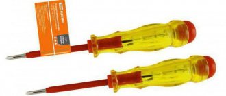
The two-pole type of indicator screwdrivers is distinguished by the fact that it has not one, but two bodies. Each is made of dielectric material and has a backlight - neon or LED lamp. Some devices are equipped with a sound signal. The two housings are connected by a wire, the length of which usually does not exceed 1 m, and both have a sting. Such devices are considered professional and are used to check the presence of current between two contacts. Among the bipolar ones, there are models that determine not only the presence of voltage, but also its magnitude.
The two-pole type of indicator screwdrivers is characterized by the presence of two bodies
Passive voltage and current indicators: operating features
The second sign of the classification of indicators is their division into active and passive devices. The basis is the functional features of the tools. Passive devices include those with the following characteristics:
- Not complicated. Single-pole, consist of one housing with elements placed in it.
- Limited functionality. The only thing that an indicator screwdriver of this type shows is whether there is voltage at a certain point in the electrical circuit.
- Unprofessional tool. Most often used in everyday life, it is unacceptable for electricians due to the lack of opportunities to provide the necessary inspection of the condition of electrically conductive cables.
The advantage of these indicators is that when determining the presence of voltage, a zero is not needed; its role is performed by a person holding an indicator screwdriver in his hands. The peculiarity of its device is also that the resistor, due to its significant resistance, does not detect the presence of voltage below 50 volts.
It is not difficult to understand how to find a phase with an indicator screwdriver of this type. You should touch the conductor with the sting, and press the plate on the device body with your hand. If there is voltage, the neon light will light up.
Passive voltage and current indicators determine only whether there is voltage at a certain point in the electrical circuit
Characteristics of active voltage indicator screwdrivers
Active indicators have a more complex structure. Inside the case there is a circuit that functions slightly differently than passive devices. This device is more sensitive. The LED voltage indicator reacts not only to the presence of current, but also to the electromagnetic field that necessarily forms around the conductor.
Active indicators have the following technical characteristics:
- Having your own power source. There is a battery inside the case that powers the internal device.
- LED instead of neon lamp.
How to use an LED indicator screwdriver? If you hold the tip with one hand and touch the plate on the body with the other, the LED lamp will react and light up. This functionality is actively used when testing wires.
Active indicators have their own power supply
Preparatory stage
Before you check the voltage in the outlet using a multimeter, you should do some preparatory work. To calculate voltage in different cases, different methods of supplying current in devices and systems are used. For example, there is alternating current in the outlet. At the same time, in accumulators or batteries the current is constant. For this reason, testers provide different operating modes. Before you start working with a certain device or system, the device must be switched to the desired mode.
Additionally, each instrument will have a specific flux in voltage measurement . And if this characteristic is unknown in advance, then the lever should be moved to the maximum position. You should also recall the purpose of the connectors located on the multimeter. The “10ADC” connector is needed to determine the DC current characteristics. The maximum allowed value is then 10 amperes.
Only the red probe is inserted here, that is, a plus.
The connector with the word "COM" is generic. Only a black probe, that is, a minus, is connected here to carry out measurements. The “VΩmA” connector is intended for various types of measurements. We are talking about resistance, voltage, current.
To carry out the work, the correct wire connection must be made. The red probe is connected to “VΩmA”, and the black one to “COM”. After this, you should move the control lever to the desired operating mode. To find out the voltage, the lever must be set to the abbreviation “ACV” or “V~”. Moreover, the position of the wheel should be set so that it is at a mark that will be higher than the expected voltage. For a regular power point, the standard is usually 220 volts. That is, it is necessary to set the nearest larger value. For most tester models, this value is 750 volts.
If the user does not even know the expected voltage and it is higher than the specified value, then this can lead to problems. The minimum would be failure of the multimeter, and the worst would be burns to the user’s hands. So before making the necessary measurements, it is better to calculate the network parameters.
Selecting the measurement mode
The presence of even minor but regular power surges can negatively affect various household appliances. Equipment with electric motors can be significantly damaged.
Lack of voltage contributes to premature wear of motor devices, and excess voltage damages microcircuits.
On any multimeter, in addition to connectors for connecting probes with cords, there must be a digital display or measuring scale, as well as a multi-position switch, through which you need to select the operating mode of the measuring device.
Basic provisions of the multimeter:
- OFF—turns off the measuring device;
- ACV - AC voltage measurement;
- DCV - DC voltage measurement;
- ASA - alternating current level measurement;
- DCA - direct current level measurement;
- Ω — measurement of resistance indicators;
- hFE - measurement of transistor parameters.
To measure AC voltage parameters, the multimeter switches to the position designated “ACV” or “V~”.
As a rule, this position assumes values of 200V and 750V. The DC voltage level is measured by switching the tester to the positions designated “DCV” or “V”. When measuring resistance levels, sensitivity indicators can range from 200 Ohm to 2 thousand kiloOhms, and when measuring DC voltage, you need to focus on sensitivity parameters in the range of 0.2-1.0 thousand Volts.
It is important to remember that the procedure for measuring current involves connecting the tester in series to the circuit, and measuring resistance and voltage parameters is performed with a parallel connection.
Standard indicators of the home electrical network
Before checking the voltage in the outlet with a multimeter or using the same device to find out the current strength in the extension cord, it is important to know what parameters to focus on for comparison.
The main indicators of the home electrical network are presented in GOST 32144-2013. Moreover, in addition to data that is incomprehensible to the average user (deviation from frequency, non-sinusoidal oscillations, lack of voltage symmetry in a three-phase network), it also indicates more understandable things:
- powered by alternating current with an oscillation frequency of 50 G;
- standard voltage and its permissible deviations - for residential and public premises for non-industrial purposes, 220 V is accepted with a permissible deviation of up to 10%, for more powerful consumers - a three-phase network with a voltage of 380 V;
- permissible rated current in the consumer - 6, 10, 16, 25, 32 A. Sockets and switches designed for a current of 6...16 A are intended for domestic purposes, 25 A - for devices with high energy consumption, 32 A - for three-phase circuits industrial value.
In this case, in the simplest ways - by plugging the device into a socket, turning on a toggle switch - you can only establish the presence of current in the network, but not the magnitude of its strength and voltage. The so-called “probes” also work—screwdrivers with a light or sound indication that is triggered upon contact with active wiring.
For a more detailed and competent study of the state of the electrical network, special multifunctional devices are used - multimeters.
Types of indicator screwdrivers
Voltage indicators, made in the form of an ordinary screwdriver, have a general operating principle, but may differ in design, functionality and design.
They are contact and non-contact.
The indicator in various models can be either a sound signal, a small LED, or even a digital screen.
Model with neon lamp
A test screwdriver with a neon lamp is the simplest tester.
The disadvantage of this contact type tool is the fairly high voltage indication threshold - from 60V.
Used to determine the phase in an AC circuit.
Not suitable for searching for broken wires.
An indicator screwdriver of the UNO type is popular in everyday life - a single-pole voltage indicator, the operating range of which is limited to the upper mark of 500V.
Used when connecting electricity meters, fuses, switches, etc.
The principle of operation of a screwdriver with a neon light bulb is that it glows when the tip comes into contact with a current-carrying conductor.
Electricity passes through the resistance resistor and is closed to the person by the second contact located at the end.
Simply put, the lamp will light up if you touch the phase wire with the tip and touch the end contact with your finger, thereby closing the circuit.
With display
Simple indicator screwdrivers equipped with displays do not use batteries, and the presence of voltage in the phase is indicated by an icon appearing on the LCD screen.
Works by reading the electrostatic field.
Typically, these tools are compact in size and the body is made of plastic.
Universal
Inside the universal indicator screwdrivers there is a microcircuit that will expand the capabilities of the tool.
There is a slider on the case - a switch through which the operating mode is selected:
• Contact testing
The presence of voltage is indicated by a built-in light.
• Contactless verification
The presence of voltage is indicated by a light bulb. The mode is characterized by low sensitivity
• Non-contact testing with high sensitivity
The presence of current is indicated by both a light indication and an audible signal.
This mode will allow you to find current-carrying wires even under a layer of plaster.
These multifunctional indicator screwdrivers are very easy to use and, most importantly, effective.
It should be remembered that the presence of additional elements in the device increases the cost of the tool.
In addition, batteries are used for power supply, which have to be changed frequently.
With LED
The principle of operation of an indicator with an LED does not differ from options with neon lamps.
But the good thing about this tool is that it works perfectly with electrical networks with voltages less than 60V.
The LED indicator screwdriver includes a self-contained power supply and a bipolar transistor, which makes this tool multifunctional with all its simplicity.
Allows you to determine the presence of a phase using both contact and non-contact methods, and check the integrity of wires and fuses.
Electronic indicator instruments
A modern version of the voltage indicator is an electronic screwdriver with a display, sound and light indicator.
In fact, this is a full-fledged multifunctional voltage indicator, the “little brother” of the multimeter.
The presence of electric current in the circuit is indicated by a phase indicator light and an audible buzzer.
The voltage value is displayed on the LCD screen.
This device is capable of working with DC and AC networks, which allows it to be used to test the networks of vehicles powered by batteries.
As a rule, this option is not common among professional electricians due to the high cost.
Battery operated
By using an autonomous power source, battery-powered indicators allow you to determine the presence of current in a phase using a non-contact method, check the integrity of electrical wiring, and find wires hidden under plaster.
No batteries
Indicator screwdrivers without an independent power source have limited functionality.
They allow you to determine the presence or absence of a phase on a conductor using the contact method.
In this case, it is necessary to close the chain with your finger, touching the contact on the end side of the tool.
This is important because the human body has natural resistance and acts as part of the circuit
How to check voltage with a multimeter
The thematic article “How to use a multimeter: detailed instructions for beginners” will help you understand the general principles of operation of the device. Here we will talk about using the device to work with sockets and other household electrical appliances.
The simplest multimeters used for household needs “can” measure current, voltage and resistance for AC and DC devices. If you need to check the voltage in a 220 V socket with a multimeter, the device regulator is set to the “alternating” voltage measurement area, marked V~ or ACV (depending on the multimeter model). In this case, taking into account the possible excess of voltage in the network of standard indicators, the regulator is set to the maximum value - 750 V. After turning on the device, the display should show three zeros (depending on the number of digits of the device - there can be from 2.5 to 8.5 - the number of zeros may differ).
Next you need to connect the probes. They are mounted like this: black in a socket marked COMMON (COM), red - or in a socket marked VΩmA.
Important: to make it easier to navigate the symbols on the front panel of the multimeter, we recommend studying the standard marking options.
The probes are installed in both sockets of the socket. The display will show the AC voltage value at that point in the network. If, when asked how to measure the voltage in a socket with a multimeter, the user is “stuck” on the choice of which hole to insert which probe into, we can reassure you. This is not important; in most modern instruments, the polarity of the probes when measuring voltage is not important.
Important: if you need to clarify how to measure the voltage with a multimeter in the socket of a low-power extension cord or in an old, Soviet-style electrical network, you can install the positive probe in the socket marked mA. In this case, overloading the device is practically eliminated.
Digital tester - detailed description
Before you measure the current in any device or determine the voltage level in an outlet, you should remember some abbreviated terms that are located on the front panels of many multimeter models:
- OFF – this position of the rotary switch indicates that the tester is turned off;
- DCV is a section of trigger movement that allows you to measure a constant potential difference in the range from 200 millivolts to 1 kilovolt;
- DCA - this sector allows you to measure direct current;
- ACV - these switch positions allow you to measure alternating voltage, the maximum value of which is 750 Volts;
- hFe – function of checking the operability of transistors;
- >l – this sector of the switch allows you to perform a function such as ringing wires.
- Ω – indicates the resistance measurement mode, usually from 200 ohms to 2 megaohms.
These testers are equipped with two probes in two colors - usually black and red. To connect them, there must be three connectors on the front panel. The red probe is connected to one of the phase connectors, the black one to the neutral one. The zero connector is marked “COM”. The red probe is connected to one of two connectors - for measuring current up to 10 amperes, or for all other measurements, designated as “VΩmA”. The same probes measure the voltage of 220 volts; you can also measure the current in the outlet and any resistance.
Before measuring the voltage in an outlet, be sure to check the integrity of the insulation of the probes so as not to be struck by an electric shock. This is the basic safety rule regarding working with the tester.
Digital multimeter: how to use?
The procedure from the moment of preparation is as follows:
- Set the preliminary range of the measured parameter. It is necessary to play it safe and put the switch in a position 10-15% greater than the expected one. In this case, even if it is exceeded, the multimeter fuse will not fail.
- Connect the cords to the connectors. Make sure that the red (negative) one is inserted into the socket that matches the type of value being measured. At the same time, the black (positive) is connected to the common COMMON (COM) connector.
- Bring the bare ends of the probes to the contacts of the circuit or part being tested. Be sure to hold the insulating layer with your fingers. The black probe is connected to the negative section, and the red one, respectively, to the positive section.
- Record the readings shown on the display. If the excess turns out to be excessive, move the rotary switch handle to a position corresponding to a lower range of the measured parameter.
Make sure that the multimeter measures exactly the value that is required in this particular case. Before switching buttons and handles, remove the probes and then touch them again to the bare contacts as described above.
Multimeter accuracy
For any multimeter, the instructions describe the characteristics, which say how much the measurement result may differ from the actual value. The digit capacity of the indicator matters. For the simplest devices it is 2.5. For precision ones, this characteristic is higher and equal to 8.5. By bit depth we mean the ability to display the result from 0 to 9 in full.
In an example it looks like this. If the digit is 3.9, the tester is capable of outputting data from 0.000 to 1.999 inclusive without switching modes. Otherwise, additional simple setup is required.
But this concerns ease of use. The accuracy of the multimeter depends on the discharge only indirectly. However, the connection is obvious. If you take a device with a bit depth of 2.5, deviations are possible within 10% in the direction of increase or decrease.
For professional work, electronics engineers buy testers with a 4.5 rating. Then the maximum error is only 0.1%. More expensive devices allow you to measure the parameters of the circuit and electrical components with a deviation of 0.01% from the readings displayed on the indicator (screen, monitor). Portable devices have a lower accuracy class than stationary, non-portable devices.
Multimeter scale markings
Analog instruments with arrows have scales, which are divided into named and conditional. Named scales are graded with measurable indicators. Conventional scales are used in instruments that are capable of measuring many parameters.
To find a numerical indicator that is measured by a device with a conventional scale, it is necessary to multiply the value of one scale division by the number of divisions on a given scale up to the interval where the arrow appears.
In addition, to determine the value of one division, it is necessary to establish the difference between the indicators of nearby divisions with numbers and divide by the number of divisions between them.
Multimeter markings
The positions of the linear or angular intervals between the surrounding scale marks, and the measured indicators, are distinguished by devices of uniform and non-uniform types.
For accurate results, a model with a uniform scale is preferred. This scale will be uniform if the ratio of the largest number to the smallest does not exceed the reading of 1.3 with a constant division value.
Near the scale on the front panel of the measuring device, the existing marking parameters are listed:
- measure of value;
- GOST, according to which the multimeter is manufactured;
- tester device; degree of protection of the device from the influence of external magnetically active and electrical environments;
- accuracy class.
In addition, it is indicated:
- tool category according to operating requirements;
- functional location of the multimeter;
- number of phases and type of current;
- experimental voltage for the reliability of electrical insulation of current-carrying elements of the invention;
- the location of the tester in comparison with the earth's magnetic field;
- the year of publishing;
- view;
- code;
- factory number and other indicators.
What if it’s not plugged in?..
Typically, all studies of household electrical networks, as already mentioned, are carried out through accessible points - sockets and switches. But from time to time it becomes necessary to check the wiring parameters where either sockets have not yet been installed (dismantled), or for some reason this is inconvenient/impossible. A good example is new buildings with “construction renovation”, where the wiring has just been installed in the apartment and there are no electrical appliances in sight except the meter.
If you need to know how to check the voltage in a 220 V network with a multimeter and still get the correct data, it is important to remember:
- the easiest way is to check the data in those places where sockets are planned to be installed or they have already been removed - there are two wires here, when connected to which the required characteristic is determined;
- mixing up the probes is not a problem. If the polarity is incorrect, the display will show the voltage value with a “-” sign;
- The main safety rule is not to touch the metal parts of the probes with your bare skin when they are in contact with the socket/wiring, and do not connect the probes in this position.
Often, beginners also ask how to check the battery voltage (on the battery) with a multimeter. In this case, the procedure is similar, but you should take into account:
- different characteristics of the electrical network and the battery - unlike household wiring, the current in the battery is constant. Consequently, the device regulator is set to the area marked DCV (V-);
- compared to the mains, the battery voltage is much lower - 1.5...24 V. Therefore, there is no need to set the regulator to the maximum value of the measured range;
- The polarity of the probes also does not matter, but it is easier to connect the red (positive) contact to the positive output of the battery, and the negative (black) contact to the negative one.
How to ring wires using a specific example
As an example, consider a standard wiring network in an apartment or private house. Ideally, all electrical communications should be made in accordance with the standards, all consumers are separated (grouped) and each circuit is powered in the distribution board through a specific machine.
Condition: the socket in one of the rooms stopped working. Task: identify the cause of the malfunction. Solution:
| The first step is to check the switchboard for automatic operation. If all the machines are in the on position, then it is necessary to de-energize the line under test (or the entire apartment). |
| Now, to eliminate the banal version of a malfunction of the socket itself, it needs to be removed from the socket box and visually inspected for defects and poor contact. Conventional sockets have a simple design. For more expensive models that have terminal blocks as clamps, it is better to ring them additionally. |
| After making sure that the outlet is working, you need to check the connection of the wires in the junction box. If there are several distribution boxes in the room, then the one you need will be located above the faulty outlet or in close proximity. |
| In the distribution box, the main cable is broken, connected to the socket wires and then goes to the next consumer (distribution box). |
| As can be seen from the example, there are three twists in the distribution box (phase, neutral, ground). When testing, the tip of one probe should touch the exposed twist. The second probe checks the socket contacts one by one. Or, if convenient, one probe is fixed in the socket contact, and the second one alternately checks the twists in the junction box. |
Having considered the main sequence of actions, we note important points and features during measurements:
- At the stage of checking the twists in the junction box, if there are no visible defects, you can additionally check the live connections. To do this, apply current by turning on the circuit breakers in the switchboard. If there are doubts about the color marking of the wires, the phase can be determined using an indicator screwdriver (when it comes into contact with a phase conductor, the indicator in the screwdriver lights up or a sound signal sounds). To find working and protective grounding, you will need a multimeter. After the phase conductor (L) is found, the ACV mode is set on the multimeter (can be indicated as V~ alternating voltage measurement) at a level above 220 V, the red phase probe is fixed on the phase conductor, and zero and ground are determined with the black probe. When in contact with the working ground (N), the device will display a voltage within 220 Volts. When the probe touches the protective ground (PE), the readings will be below 220 Volts. After checking, the apartment (room) should again be de-energized.
- Next point. It is not always possible to be absolutely sure that the wires from the outlet being studied go to the nearest junction box. It happens that sockets, bypassing distribution boxes, are powered with nearby sockets. A connection is also common, when two sockets in adjacent rooms are mounted at one point on a common wall. All this needs to be analyzed and taken into account.
- The issue of convenience of measurements is very relevant. After all, as a rule, the socket and the distribution box are located at a considerable distance, and the measuring probes of the multimeter often have a length of 30 - 50 cm. In this case, for convenience, you can insert a jumper into the socket (connect two contacts), and perform the test directly in the distribution box box. A more accurate measurement can be made by connecting the outlet to a working extension cord.
Security measures
Now let's talk about safety measures that you should know when carrying out this type of work. The first thing you should know is to avoid touching the parts with your fingers. The fact is that the human body has resistance, which will affect the accuracy of measurements and can distort them. Another aspect is that if the master does not have information about the pre-voltage in the network, then you can measure the indicators so that the control wheel is set to the highest value in volts.
In addition, it is best to carry out work wearing special dielectric gloves . Although ordinary rubber or household ones may be suitable. When determining line resistance, it is best to ensure that the power is completely turned off and the capacitors are completely discharged.
In addition, when working with a 20-amp power point, measurements should be taken no more than a quarter of a minute. Also, you should not check the network performance with a tester if the room humidity is high . In addition, the control wheel must not be turned under any circumstances while taking measurements. Also, you should not use the device if the braiding of the probes is deformed and there is serious damage to the body.
The battery of the device should be replaced only after the wheel has been switched to off mode. After this, the used battery is disposed of. Under no circumstances should it be thrown away with household waste. When measuring the internal resistance of a circuit, make sure that it is not energized so that the tester is not damaged. There are standards for the operation and storage of such a precision instrument as a multimeter. Do not apply voltage to the device if the rotary type lever is at “Ohm”.
In addition, the device in question should not be used if the housing cover is not securely or completely closed.
An equally important aspect is that replacing a galvanic-type battery should be done not only when the device is turned off, as mentioned above, but also when all probes are disconnected from the multimeter sockets. Measuring the voltage in an outlet with a multimeter is a rather responsible process. The person who is going to carry it out must have certain theoretical and practical knowledge, as well as take into account certain standards and requirements that are put forward for the equipment.
But, nevertheless, with all the necessary knowledge of a theoretical and practical nature, even a person who has never done anything like this before can carry out this type of measurement . The main point will be the correct setting of the expected characteristics of the electrical network, because it is this aspect that most often leads to equipment breakdowns, since users do not pay due attention to it. Therefore, we should once again recall the importance of this particular component.
Possible problems
No device, including a digital multimeter, is capable of displaying incorrect or incomplete data, or not displaying it at all.
Doesn't turn on
If the tester does not show anything, check whether it is turned on at all. Next, check to see if there is a battery in it, and whether it is so discharged that it stops turning on. Check if the display is intact. If the tester is turned on, but with a new battery it does not show anything, the reasons are as follows:
- the power cord or terminal has fallen off, the battery is damaged or its contents have leaked;
- the device fell, hit, got wet, causing the display to lose contact with the interface module (digital matrix controller);
- when exposed to aggressive chemicals, liquid crystals leak out and the reflective film is damaged - the screen becomes not only inoperative, but whitish;
- The central microcircuit that controls the operation of the device is faulty.
If you have the necessary repair knowledge and skills, you can disassemble the device. You are quite capable of finding out what is wrong with it. In the latter case, when the ADC (microchip with converter) does not work, the multimeter cannot be repaired. The only exception is the situation when you have another multimeter at hand, in which the screen, buttons and/or switch are damaged.
Exaggerates voltage values
If the battery is low, the device will start to lie. There have been cases when the “outlet” voltage instead of 220-240 V showed, for example, 260-310. This happens when the battery is discharged to 7-8 volts. Replace the battery with a new one and repeat the measurements in the same place. Most likely this problem will be resolved.
The display is too “faint” or “bright”
A slight highlighting of all sectors of numbers against the background of the required ones (for example, number 8 against the background of number 3) is an indicator that you came across a battery with a voltage that accidentally turned out to be higher than 9 V, for example, 10.2). This also occurs when the tester is forcibly powered from an outlet using a 12-volt power adapter, which is an excess. Do not supply power with voltage greater than 9V.
The pale glow of the display sectors (the numbers are barely visible) indicates that the battery is discharged to 6 V, and the multimeter is about to turn off. Change the battery.
Incorrect display of numbers
For example, if instead of the number “8” you saw a capital “L”, “stroke”, “space”, “minus”, capital or lowercase “P” (or “U”, “C”, “A”, “E” ), “soft sign” (all this should not happen), then the display controller has failed. In some cases, the corresponding elements of the digital matrix may be partially damaged.
If you have a working matrix from exactly the same tester in which the “motherboard” burned out or crashed, you can rearrange the surviving display from it and then compare the results. If the same problems are detected, suspicion already falls on the display controller. There is nothing you can do here. Buy a new multimeter.
The beeper does not work in dialing mode
Some multimeters have a button that turns off the beeping of the device when the line is dialed. Make sure the alarm is not turned off. Otherwise, the “beeper” wire has been disconnected from the board, or it is defective or damaged during a previous careless repair of the device. Install a sound emitter from another similar tester. You can work without it.
Backlight doesn't work
If you did not turn off the backlight using a special button or the battery did not run out, then a sign of a non-working backlight may be defective or fallen off LEDs. Check (and replace) them. You can work without backlight.
Slow operation of the device
Slow response of the multimeter to changing conditions, such as connecting other resistors, indicates defective auxiliary parts on its board. So, if the resistance does not change immediately when adding a resistor, in standby mode the last digit “0” changes to “1” and back, then the reason is a malfunction of the capacitors on the device board.
The screen turns on and off
When the screen lights up at startup, but goes out a few seconds after turning on, the problem is in the multimeter’s master oscillator. Since the SG is part of the main microcircuit, you are unlikely to achieve anything here; this element cannot be replaced. The entire device must be replaced.
Why know the voltage in the outlet?
The outlet is carrying alternating current. This means that deviations from the nominal value occur, up or down. The nominal voltage in Russia is considered to be 220 Volts, but in fact the value is 230 Volts. Modern household appliances are created taking into account permissible deviations; exceeding the specification can cause damage to the devices. Devices with electric motors (air conditioners, refrigerators) are especially susceptible to influence. To reduce the risk of breakdown, you need to be able to determine voltage using special testers.
Many people believe that this skill is not necessary for the average user and is only needed by specialists. This is not so, because fixing the socket, checking the presence of a network in the apartment and other work related to wiring begins with determining the voltage.
Which wire can you touch in a live socket? Phase or zero?
Since we are in the electrical safety section, we will also discuss the issue of touching the neutral and phase wires in the socket. Electricity will not be disassembled by accident or on purpose, the result will be the same.
We immediately touched the phase and zero
A current flowed through you of the same magnitude as U/R. Where R is your internal resistance, which depends on various factors. That is, the current will flow and you will be sad or posthumous. There are several ways current flows through a person.
Touched the phase conductor:
If you are soaring in the air like a bird or standing on a dry wooden stand, plus you don’t touch grounded objects with other parts of your body, plus a bunch of other factors that you “took into account” (although most likely you didn’t take into account, but circumstances just happened that way) => Then you will not will give you an electric shock.
Note: Let's assume that the situation was such that you survived. And you tell everyone that this is how you can do it. Someone will listen to you and repeat, but with a sadder outcome. Either because of a wet floor or hands, or because of accidental contact with a grounded equipment case. This means that you doomed a person to disaster, only because you used the “survivor effect”. Is not cool.
Touched the working zero:
Nothing will happen to you only if the load in the network is symmetrical in all three phases, and the current does not flow in the neutral wire (more about neutral displacement), and this is a rare case that can sometimes occur in production.
It is always easier to turn off the power and carry out the necessary work than to put your life at risk. As they say, safety rules are written in blood. But I do not deny that there were people who took up the phase and neutral wires and got nothing. Simply playing with electricity will not lead to anything good. It's like walking blindly through an unmarked highway at night.
Personally, I always use the following rule: if you want to tinker with sockets or switches in the apartment, turn off the input circuit breaker and make sure that no one turns it on.
What will it show if the socket is faulty?
If there is no network, the multimeter will read 0 Volts. The reason is a faulty socket or lack of electricity. To determine the cause, you need to ring other outlets in the room. If only one does not work, its contacts are checked and, if necessary, replaced with a new one.
During voltage surges, the values on the multitester will differ greatly from the nominal 220 Volts. According to GOST, a deviation of 10% is permissible; a larger deviation can lead to damage to electrical appliances. If a strong voltage surge is detected, it is worth installing an additional stabilization device in the apartment.
The home network operates at a voltage of 220 Volts, but in the outlet it may differ from the nominal value. Voltage within the limits established by GOST is the key to high-quality and stable operation of household appliances. It is important to be able to check voltage using a multitester to prevent the risk of damage to electrical devices. If there is a significant deviation from the set values, care should be taken to stabilize the voltage in the room.
Difference Between AC and DC Voltage
It would be more correct to talk about the difference between direct and alternating current. Various electrical appliances operate on either direct current or alternating current.
Variable means that the direction of movement of electrons in a conductor changes from plus to minus with a given frequency, that is, the polarity of the current changes. In a household outlet, according to the standard, the effective voltage is 220 V (amplitude 311 V) and the frequency of current change is 50 Hz. All devices that are plugged into an outlet operate from this voltage.
But accumulators and batteries are sources of direct current. They always have a fixed plus and minus (polarity). Naturally, direct current has no frequency.
Measuring AC current with a voltmeter
If you need to measure the strength of alternating current, but you only have a budget multimeter at hand, which does not have such functionality, then you can get out of the situation by using the measurement method using a shunt. Its meaning is reflected by the formula I = U / R, Where I is the current strength that needs to be found, U is the voltage in the local section of the conductor, and R is the resistance of this section. From the formula it is clear that if R is equal to one, then the current strength in the circuit section will be equal to the voltage.
To measure, you need to find a conductor with a resistance of 1 ohm - this can be a fairly long wire from a transformer or a piece of spiral from an electric stove. Wire resistance, i.e. its length is adjusted by the tester in the appropriate test mode.
The result is the following circuit (incandescent lamp as a load):
- From the first connector of the socket, the wire goes to the beginning of the shunt, and one of the multimeter probes is connected here.
- The second probe of the multimeter is connected to the end of the shunt and from this point the wire goes to the first contact of the lamp base.
- From the second contact of the lamp base, the wire goes to the second connector of the socket.
The multimeter is set to AC VOLTAGE MEASUREMENT MODE. It is connected in parallel to the shunt, so all the rules are followed. When the power is turned on, it will show a voltage equal to the current passing through the shunt, which in turn is the same as the load.
Wire resistance measurement
This is the simplest mode of operation - essentially you need to take a wire, for which you need to measure the resistance and touch the ends of the multimeter with the probes.
Resistance measurement occurs thanks to the power source that is inside the multimeter - the device measures its voltage and current in the circuit, and then calculates the resistance using Ohm's law.
There are two nuances when measuring resistance:
- The multimeter shows the sum of the resistances of the wire being measured along with the probes that touch it. If exact values are needed, then the probe wires must initially be measured and then the result obtained should be subtracted from the total.
- It is difficult to estimate in advance the approximate resistance of the wire, so it is advisable to make measurements by reducing the sensitivity of the device.
How to Measure Battery or Battery Voltage
All kinds of batteries and various accumulators, in general, everything where you see “+” and “-” are all sources of direct electric current. Measuring DC voltage is no more difficult than alternating voltage.
To do this, take, for example, the most ordinary AA battery. Connect the red wire of the multimeter to “+” terminal of the battery, and the black wire to the “-” terminal of the battery . If you connect them the other way around, nothing bad will happen, the readings will simply be displayed on the multimeter screen with a minus sign, something like this.
Usually the voltage on the batteries is low, so you don’t have to be afraid to press the probes with your fingers. Up to 20 volts you most likely won't feel anything. In the case of an AAA battery, its maximum voltage is 1.5 volts, which is not at all dangerous for a person.
As we can see from the multimeter readings, the voltage in our battery is 1.351 volts, which means the battery is still fully charged and can be used.
In a similar way, you can check any other batteries and measure their voltage, and as you now know, there is nothing complicated about it.
Motorcycles and cars
Cars and motorcycles have occupied a significant niche in our lives; every family simply must have a vehicle. This type of charger is used for cars and motorcycles that are rarely used and therefore are not charged from the generator. The difference between such charges and others is their greater power, which produces a large current at the output.
The first step is to measure the output voltage of the charger. If the battery is fully operational and charged, then the voltage at the output should be in the range of 13.2-14.4 V. To measure the voltage, you need to switch the toggle switch on the multimeter to DCV mode. In this case, provided that charging when the battery is completely discharged will not produce a voltage at the terminal of 13.2 V, the use of this device is undesirable. You also need to check the charging housing if it is allowed by the design.
To check the strength of the charging current, you need to switch to the ammeter mode, which is connected in series to the circuit. You also need to take into account the control of the charger; if it is manual, then you need to set the current using a switch, and if automatic control is provided, you must take into account that the battery capacity should not be less than one tenth of the total volume.
Checking the diode with a multimeter
The diode only conducts current in one direction, so two measurements will be required to check for functionality. In the first position there is conductivity, in the second there should not be. A breakdown is indicated by two cases when the current does not flow in both directions or vice versa, if the readings are zero in any of the cases. When checking, the handle is moved to a position whose range satisfies the nominal characteristics of the diode being tested.
Analogues of the Duwi and KVT socket testers - which is better?
Other manufacturers also have similar testers. For example duwi or KVT MS686ODR.
However, they lack the ability to check voltage. Sockets are tested in the same way.
You plug in the tester and by the flashing indicators you get the information you are interested in. Fortunately, everything on these testers is written in Russian and there is no need to translate anything.
For example, checking the carry.
As you can see, the middle LED is blinking. This means that there is no grounding in the carrier. Unfortunately, this picture occurs all the time. Therefore, when choosing extension cords, be extremely careful.
Unfortunately, the functionality of similar devices from KVT and other manufacturers is slightly limited and they lack a voltage display. And this is perhaps the main thing that interests the average consumer.
You can get acquainted with an adequate price and order such a miracle Habotest tester from our Chinese comrades here.
Tester operating instructions (in English)
As a result
Even a budget universal measuring device - a multimeter - allows you to take measurements within a fairly wide range, sufficient for home use. But when buying a device, you need to at least have a general idea of what purposes it will be used for - it may be better to overpay a little, but as a result, have a tester on hand that can perform any task assigned to it. Also, before using it, it would not hurt to at least in general refresh your memory of the basics of constructing electrical circuits and using electrical measuring instruments in them.
Sources
- https://stroy-podskazka.ru/multimetr/proverit-napryazhenie-v-rozetke/
- https://stroy-okey.ru/house/instrument/kak-proverit-naprjazhenie-v-rozetke-multimetrom/
- https://instanko.ru/instrumenty-i-materialy/tester-elektricheskij-multimetr-instrukciya-2.html
- https://electric-220.ru/kak-proverit-naprjazhenie-multimetrom
- https://pomegerim.ru/electrobezopasnost/sila-toka-v-rozetke.php
- https://domikelectrica.ru/kak-proverit-rozetki-v-kvartire/
- https://YaElectrik.ru/elektroprovodka/kak-proverit-napryazhenie-v-rozetke-multimetrom
[collapse]
Similar posts:
- Calculation of cable cross-section by power: formulas, tables,…
- Location of sockets in the kitchen: diagram with dimensions,…
- Connecting the hob to the power supply yourself
- How to connect a phone socket yourself
- Triple socket: installation diagram, with and without grounding,…
- Oven socket: what kind of socket is needed for...