Installation required
Grounding is effective when a phase conductor breaks down on the housings of devices, equipment, or conductive parts of structures. The presence of grounding will prevent electric shock, as it will eliminate the occurrence of a potential difference between the device body and the ground.
How can you improve the safety of operating an electrical network in a room without grounding if it is not possible to replace the electrical wiring? There is an exit.
Often, property owners or premises owners find themselves in a quandary, wondering whether it is possible to install residual current devices or differential circuit breakers in a two-wire single-phase network when there is no grounding?
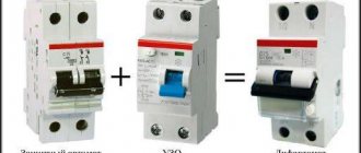
It is not only possible to install, but also necessary. Moreover, even in the presence of grounding, the use of differential protective devices is recommended, and in some cases mandatory. Such devices are installed in a single-phase two-wire network on both conductors at once.
Installing the device in a two-wire network
It is recommended to entrust this important work to a qualified electrician. If such an opportunity is not available, but you have at least minimal knowledge in electrical engineering, it is recommended to adhere to a number of rules:
- The power of the differential switch should be one step less than the power of the RCD. For example, for a 40A/30mA residual current device (the latter indicator indicates the leakage current), a 25 Ampere switch is required.
- If the wiring of the electrical circuit is complex, the amount of current leakage can be significantly more than 30 mA. The consequence of this will be frequent false alarms of the protective shutdown device. This course of events is avoided by dividing the total network load into two independent RCDs. Moreover, each of them can withstand a leakage of 30 mA, and this should be enough.
- In the electrical circuit of the bathroom you will need a differential switch with an operating threshold of 10 mA. For the bathroom, a 25A/10 mA RCD is recommended.
- According to the regulations, it is not allowed to install a differential switch upstream of the meter. According to his instructions, the inspector of the energy sales organization will force you to dismantle the device to prevent the receipt of electricity bypassing the meter.
- In addition to the residual current device for sockets, a 16 Ampere circuit breaker is installed.
- A 10 Amp RCD is installed to the differential switch for light switches in the house.
- It is recommended to install not a single-pole, but a two-pole device. This ensures greater security of the system, since it allows you to open not only the phase, but also the zero when the network is overloaded.
- When connecting a residual current device, you should strictly follow the instructions located on the device body.
- The differential machine is installed in a place inaccessible to random persons. However, if necessary, the machine must have free and quick access by specialists.
When all residual current devices are installed in place, their functionality is checked. The main task is to check the system for false positives. To check, connect the machine located in front of the device, the differential switch. Next, press the “Test” button on the device. If this is followed by a shutdown, the device is operating correctly.
Note! According to the standards of the PUE (Electrical Installation Rules), the installation of residual current devices in the networks of the TN-C subsystem is not permitted. If it is necessary to protect the electrical receiver, the grounding PE conductor is connected to the PEN conductor. Thus, TN-C is transformed into the TN-CS subsystem.
Protection against electric shock
The operation of a differential circuit breaker or residual current device (sometimes called differential relays) is based on determining the difference in phase and zero currents.
If a difference exists, the device turns off the electricity supply. The difference can be recorded when a current leak occurs. When an electrical appliance or equipment is in good working order, there is no leakage in it, that is, the value of the current flowing through the phase conductor is equal to the value in the neutral conductor.
If the insulation of a phase wire is damaged, a potential difference arises between it and any grounded object. The same thing happens when there is a breakdown on the body of an electrical device. Grounding in this case will only help remove this potential difference from the housing, but the device itself will remain energized.
If a person touches the body, the latter most likely will not feel the impact of electricity, because the resistance of the body is greater than the resistance of the grounding conductor. You can imagine what would happen if the grounding is faulty or absent altogether.
If such a situation occurs, the differential machine will turn off the electricity supply and de-energize the device. A person, even if exposed to electricity, will not feel it, because the current value will not exceed 30 milliamps, and the shutdown time will not exceed 0.3 seconds. Such parameters for RCDs and automatic circuit breakers used in residential premises are determined by the standards.
Operation of a difavtomat in a two-wire circuit
The operating principle of a differential device is reminiscent of an analyzer that compares the indicators of currents flowing through the phase and neutral conductors. If deviations in values occur due to a leak (for example, after a short circuit to the refrigerator body), the relay contacts of the difavtomat open and the network is de-energized.
As an example, let’s look at a situation where the insulating layer of the electrical wiring in a washing machine was damaged. Touching a bare current-carrying conductor to a metal casing causes current to spread where it should not exist. As soon as a person touches the washing machine, he will get an electric shock. Moreover, the victim will remain under tension as long as he touches the body (and it is difficult to tear himself away from it). In such a situation, an RCD or automatic circuit breaker comes to the rescue, turning off the current in the circuit.
Scheme selection
In a three-wire network with a grounding wire, it is allowed to connect a breaker or RCD in separate rooms or to separate groups of consumers. The remaining groups are protected by installing a circuit breaker with a rated current corresponding to the load.
In a two-wire network, the connection diagram must provide for the presence of a protective device at the entrance to the distribution board. Only if this condition is met will all electrical wiring be protected.
For correct and reliable operation of electrical wiring in a two-wire network, it is advisable to install differential circuit breakers or residual current devices on each group.
Each circuit must be protected by a separate device. The input circuit breaker must have rated current parameters that are not less than the total that can occur in protected circuits.
The differential current of this machine must be at least 100 milliamps so that the machine does not operate simultaneously with any of the subsequent ones. It is also necessary that the input difavtomat be designed for selective operation in circuits. In this case, there must be special markings on the device body.
RCD selection
The circuit breaker is designed to operate with an overload for seconds or even minutes. The protective connection device is not able to withstand such loads and will most likely fail. Small power devices are used with a current of 10 Amps or less. For powerful devices you will need a reserve of 40 Amps.
If the voltage in the living room is 220 Volts, buy a two-pole device. For 380 Volts, a four-pole device is required.
The leakage current indicator of the residual current device determines which device is needed: fire protection or current protection. The devices are capable of operating at different speeds. For fast response, selective devices are used, which come in two classes (S and G). Devices marked with the letter G have the highest response speed.
The machines are available in electronic or electromechanical versions. For electromechanical devices there is no need for additional power supply.
As for the type of leakage current, information about this is indicated on the housing. AC stands for alternating current, and A indicates both alternating and direct current.
Connection rules
When using several differential devices in a wiring diagram, there may be cases of incorrect operation of the differential devices. They may either turn off when a load is connected, or they may not operate even if there is a leak.
If you know how to properly connect a circuit breaker to a network without grounding, you can avoid many mistakes and save time on debugging the circuit . Simple connection rules are described below:
- The power supply of the difavtomat is connected from above to the terminals with screw clamps. The load is connected to the lower terminals. In this case, phase or polarity must be observed;
- The difavtomat must be connected to the gap of both conductors with single-phase wiring, otherwise, if any conductor bypasses the device, it will be triggered when the load is connected;
- phase and zero in one separate socket must come from one difavtomat, if in the socket the phase is from one difavtomat, and zero is from another, both machines will be turned off;
- an electrical appliance or group connected to one machine must not have contact with devices of another group. Often, to save space in the switchboard, all neutral conductors from the loads are connected to a common bus, connecting all the circuit breakers via the neutral wire. As a result, each difautomatic device detects the zero of the neighboring group, like a conductor with a leak, since part of the current returns through the neighboring device.
Checking the correct connection can be controlled by pressing the “TEST” button on the body of the difavtomat. If connected correctly, it should turn off. This is a necessary condition, but not sufficient.
Sometimes when the “TEST” button is activated, the machine still turns off when the load is connected. The reason may lie in a violation of the rules described above.
If the parameters of the differential circuit breaker correspond to the wiring diagram and the connection is made correctly, then this device is the only reliable means of ensuring electrical safety in the absence of grounding.
Connection diagrams
Regardless of the circuit, the circuit breakers are connected to the phase or neutral of only the circuit for which they are needed to protect.
RCBO at the input
The device is installed in the panel and protects the wiring branches and groups to which they are connected. The input machine must be selected taking into account the power and operating characteristics of the network. First, the counter is installed, and then the device. All electrical circuits are connected to the output of the RCBO. An individual limit switch is installed for each circuit.
Portal about construction
Special residual current devices (RCDs) are recommended to be installed where there is a high probability of electric shock. The purpose of the device is to quickly turn off all electrical equipment if a leak occurs on the housing. The device operates according to a circuit that does not require an additional connection to grounding. It is also possible to fully connect an RCD with grounding: it works well both if there is a working ground wire, and if something happens to it. The principle of direct grounding is similar to the principle of operation of the device: if there is a threat of a short circuit in the network, automatic protection is triggered, de-energizing the equipment. The same goal can be achieved in two ways:
- install protective grounding;
- connect the RCD under the condition that the conductor is not grounded.
Features of connection in a private house
The electrical network in a country house is not fundamentally different from that in an apartment, but more diverse options are appearing. For example, it is easier to install one single device at the input or several residual current devices on the most important lines of the network.
The 300mA input device protects all electrical wiring from fire. The RCD is capable of responding to the total leakage current from all existing lines, despite the fact that the standard is observed in each individual case.
Universal devices designed to operate at 30 mA are installed after fire protection devices. The next lines are the bathroom and children's room (Iу indicator = 10mA).
Conversion of the grounding system to TN-CS is allowed. Independent connection of re-grounding to the neutral is not allowed. If voltage gets to the neutral wire from the external network, grounding will become the only one for the surrounding houses, which, if the work is done poorly, becomes a frequent cause of fires. It is recommended to perform repeated grounding at the input site from the overhead power line.
The connection diagram for a residual current device in a small country house is usually the simplest, since the loads are relatively small. Most often, connection to a single-phase network and a 30mA device are selected. The device is universal and allows you to protect yourself from both fire and voltage.
In country houses, a main input and two circuit breakers are installed (for sockets and light switches). The boiler is connected to the network using an outlet or a dedicated machine.
Is it possible to install an RCD in a network without grounding?
The design of protective devices is variable: it can only have phase and zero terminals. Does an RCD work without grounding?
A two-wire system without grounding was used in the construction of houses during the existence of the Soviet Union. Schemes with the third phase are typical for newer buildings. In old houses with a two-phase system, it is possible to connect an RCD with or without grounding. You can notice the difference only at the moment of operation: a circuit with grounding will make an emergency shutdown of all devices as soon as a current leak is detected, and in an RCD circuit without grounding, the protection will only work if you touch a device that is energized. If a protective mechanism is connected, the systems operate instantly, preventing the possibility of electric shock.
Operating principle and features of RCD
The connection diagram is simple: one phase and one neutral wire passes through the device. The device “reads” and records the load indicators applied to the wires and compares them with specified standards. If the wiring is damaged or a leak occurs, current “flows” to the surface. Even at a minimal value (only a few tens of milliamps) it can cause serious damage to human health. An RCD without grounding equalizes the current passing through the phases and, if deviations in the current values are detected, it performs an emergency automatic shutdown of a section of the network. Are you wondering “what will change if I connect an RCD”? The answer is simple: your circuit will become protected, because upon detecting a leakage of current that enters the body of the water heater, the device will completely de-energize the damaged section of the circuit.
Types of RCD
RCDs are divided into several main types.
Depending on the installation method:
- Portable (installed directly into an outlet).
- Stationary (initially built into an outlet or installed in a panel).
Depending on the trigger method:
- A device with an additional power source.
- Device without additional power source.
Depending on the number of phases:
- Single-phase 4 contacts.
- Two-phase 6 contacts.
- Three-phase 8 contacts.
Depending on the adjustment features:
- Unregulated.
- Adjustable (available with smooth and discrete control).
Depending on the principle of operation during pulse jumps:
RCD connection options
- One powerful protective device is installed over the entire network. The advantage of this method is its simplicity: the phase conductor passes through the device itself to the RCD terminals and is connected to circuit breakers, through which it is connected to all electrical equipment. This miniature-sized circuit also has its drawbacks: firstly, the operation of the RCD leads to the shutdown of all electrical equipment in the apartment or house, and, secondly, it will be quite problematic to determine the location of the insulation breakdown or the presence of other faults.
- Separate RCDs are installed on each dangerous section of the network. The disadvantage of this connection scheme is significant material costs and large dimensions of the device. The advantages are obvious: de-energizing one area will not lead to a shutdown of equipment in the entire house (apartment) and identifying the cause and location of the malfunction will be quite simple. Connection diagram: the phase wire, leaving the meter, passes through each circuit breaker and RCD.
- Connecting an RCD with grounding, which is characterized by balanced current in three phases. It is excellent when there is an equivalent phase current load. It is considered unacceptable to connect an RCD with grounding in cases where the voltage in the phases does not match: in this case, the RCD will trip constantly.
Expert advice
When choosing an RCD for installation in a private house or apartment, you should immediately abandon electronically controlled devices. If the power supply to the electronic circuit is disrupted for any reason, its performance will be incorrect and the device will no longer perform its assigned task. And failures of this device can lead to tragedy. Add a circuit breaker to the general circuit diagram for connecting an RCD without grounding. An RCD can provide full protection in the event of a current leak, but it is not designed to protect the network from short circuits or overloads. The combination of the two devices will help protect against fires, equipment damage and electric shock.
When you connect a residual current device from the network, do not forget that after the RCD it is unacceptable to create a single unit from neutral conductors. A circuit created in this way will cause constant false alarms of the device and its incorrect operation.
After installing the entire circuit, check how correctly you have reproduced the circuit. To do this, simply connect any electrical appliance to an outlet that is on the same circuit as the RCD. If the RCD does not turn off, then everything is done correctly. You can test the operation of the device for operation very simply: just press the test button located on the body of the RCD.
Connection errors
It is important to connect an RCD with grounding as correctly and correctly as possible, avoiding the most common mistakes that can lead to unexpected results.
- In no case should you connect the grounding conductors of sockets to a man-made grounding or neutral conductor to increase network security. Such actions are dangerous to life and health: only high-quality, proven grounding will provide the required level of protection.
- You should not try to connect the grounding conductors of sockets to various conductive engineering structures installed in buildings. The reason is still the same: it is very difficult to do it correctly, there is a high probability of receiving serious injuries, including those incompatible with life.
- Under no circumstances should a neutral wire be connected to ground (this manipulation is carried out supposedly to increase the level of reliability of the entire system).
- If for any reason the grounding stops working, then the best solution is to disconnect and apply insulation to the grounding conductor connecting the electrical appliances to the panel. Inaction in such a situation can lead to all electrical appliances in the room being energized.
- If you are not sure of the correctness of your own actions, then you do not need to act on the “I’ll connect somehow” principle. It is better to entrust the installation of RCDs to professionals with experience, because human lives depend on how correctly the system is installed.
Three-phase automatic machines
A reliable three-phase automatic circuit breaker
is a device for ensuring the safety of electrical networks that are laid in industrial enterprises, office buildings, municipal institutions and private homes. Its installation allows you to solve two problems at once. The first is to protect against short circuits, and the second is to ensure the safety of the health of people and pets. To select such a protective device, its characteristics should be identified in advance.
In our company you can use a three-phase differential automatic machine
, designed to solve a number of problems. Firstly, you save space for installing switchboard systems. The fact is that without it you will have to install a circuit breaker and an RCD. Secondly, thanks to it, you will achieve the most effective protection of electrical equipment, and your own home, from short circuits and power overloads. In order to correctly select and buy a 3-phase automatic circuit breaker, you should know the rated voltage and phase of the electrical network. In addition, the current rating parameter is important. We provide a guarantee for all products sold by our company.
- View as
- Table
- List
The differential circuit breaker AD-2(4)(S) of the EKF PROxima series is a device that combines the functions of a circuit breaker with a residual current device. When a circuit breaker detects a leakage current (damage) to the ground or an overcurrent (overload current or short circuit) in the protected section of the network, the device is triggered, leading to the shutdown of the protected network.
The differential circuit breaker AD-32 of the EKF PROxima series is a device that combines the functions of a circuit breaker with a residual current device. When a circuit breaker detects a leakage current (damage) to the ground or an overcurrent (overload current or short circuit) in the protected section of the network, the device is triggered, leading to the shutdown of the protected network. A special difference between EKF differential circuit breakers is that they are available.
The differential circuit breaker AD-32 of the EKF PROxima series is a device that combines the functions of a circuit breaker with a residual current device. When a circuit breaker detects a leakage current (damage) to the ground or an overcurrent (overload current or short circuit) in the protected section of the network, the device is triggered, leading to the shutdown of the protected network. A special difference between EKF differential circuit breakers is that they are available.
The differential circuit breaker AD-2(4)(S) of the EKF PROxima series is a device that combines the functions of a circuit breaker with a residual current device. When a circuit breaker detects a leakage current (damage) to the ground or an overcurrent (overload current or short circuit) in the protected section of the network, the device is triggered, leading to the shutdown of the protected network.
The differential circuit breaker AD-2(4)(S) of the EKF PROxima series is a device that combines the functions of a circuit breaker with a residual current device. When a circuit breaker detects a leakage current (damage) to the ground or an overcurrent (overload current or short circuit) in the protected section of the network, the device is triggered, leading to the shutdown of the protected network.
Does an RCD without grounding work or not?
Modern apartments and private houses are equipped with a large number of different household appliances. In this regard, protecting people from electric shock comes to the fore. The main priority protective measures are the installation of traditional circuit breakers - automatic machines and residual current devices - RCDs. However, in each specific case, in the presence of single- or three-phase networks, questions of a technical nature arise, for example, does an RCD without grounding work or not? In many old houses there is no grounding, so the possibility of using protective devices in these conditions is of particular relevance.
Is it possible to install an RCD if there is no grounding?
All experts talk about the importance of installing RCDs in places where there is an increased probability of electric shock, and this should not be neglected. Some experienced specialists argue that connecting this device without grounding it in two-wire electrical networks is impossible. This leads to the fact that you will have to upgrade your home network, but this is expensive. In addition, you will have to completely abandon protective shutdown devices.
Appearance of the RCD
Note! This belief is incorrect, since the protection device has only two connectors for phase and neutral, and there is simply nowhere to insert the grounding. Moreover, the design features of these devices and their operating principle allow them to function quietly even without grounding.
This fact is confirmed by cases where the residual current device was connected to a three-wire electrical network and worked for a long time and without any failures, even in cases where the grounding cable was disconnected or broken.
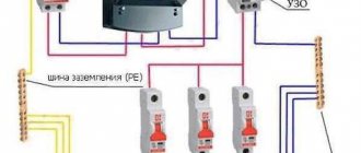
Popular diagram for connecting an RCD without grounding in an apartment
Is grounding required for RCDs?
Many homeowners are confident that the protective device will work correctly only if there is a three-wire electrical circuit, with phase, neutral and ground conductors. For the same reason, the question often arises: which is better? RCD or grounding. In order to give the correct answer, it is necessary to understand the purpose of each of them.
It is known that the main function of an RCD is to turn off equipment when a current leak appears on the housing. Thus, it is possible to avoid electric shock to a person. Grounding is installed for the same purpose, only it works according to a different scheme. When electric current appears on non-current-carrying parts, a short circuit is created due to grounding. As a result, the maximum current protection of the machine is triggered and the equipment is de-energized.
Consequently, both methods of protection can be used separately, and, if necessary, together, complementing each other. Therefore, mandatory installation of grounding when using an RCD is not required and the protective device can be used even in a two-wire single-phase network in which there is no standard grounding. This conclusion is confirmed by the design of the device itself, where there are phase and neutral terminals, but there is no separate terminal for the ground wire. Particular attention should be paid to this, since grounding is mandatory only in modern houses.
In old houses, built during the Soviet era, two-wire networks are still used, without a grounding conductor. In such cases, protective devices are especially necessary. The only difference in the operation of an RCD with grounding and without grounding is only in the response time. In the presence of grounding, operation occurs almost instantly. An RCD without grounding is triggered only at the moment of touching the body of the device, which is energized. Therefore, the degree of protection is no longer as reliable as in the first option, but nevertheless, even in this case, the RCD protects against the unpleasant consequences of electric shock.
Installation and connection
Before directly starting to connect the difavtomat to a single-phase or three-phase network, it is installed in an electrical panel. Installation does not involve any complex actions and can be done even by a less experienced person.
According to the recommendations of electricians, the device must be carefully checked for cracks and chips before installation. Next, you should de-energize the input line. To do this, the input machine located in front of the meter is usually turned off.
The differential protection module itself is mounted on a DIN rail pre-installed in the panel. This bar has protrusions on the top and bottom sides, and the product being installed has a latch on the back side.
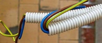
To connect them together, the upper mount is put on the rail, and then with a little force the bottom of the device is pressed until it clicks. After that, the machine can be moved in a horizontal plane to any place along the entire length of the DIN rail. The insulation is removed from the required wires - about 10 mm - after which they are inserted into the sockets of the machine and pressed with screw clamps. There is a rule that the input wires are inserted from the top, and those going to the load from the bottom. The color marking of the wire is also maintained: phase wires are brown, neutral wires are blue, and ground wires are green.
Once the device is installed in its place, proceed to its connection. At the same time, the difference between a single-phase network and a three-phase network lies in the number of current wires: 1 or 3, and the connection principle is the same. There are three types of connection:
- introductory;
- selective;
- with grounding.
Typical switching
The most common option is to connect a difavtomat as an input device. This arrangement implies its installation immediately in the line after the meter or the introductory separate machine. There is no fundamental difference where to install the device: before or after the introductory batch switch.
The connection occurs as follows: the phase wire coming from the meter is inserted into the upper terminal of the device, designated on the case by the Latin letter L, the neutral wire is fixed in the terminal labeled with the letter N. From the lower contacts of the difavtomat, the neutral wire is inserted into the neutral block, and the phase wire is connected to the packet switches. Then from each switch it is directed towards the load it protects, and the neutral wire with the block terminal is pulled there.
This connection allows you to protect all wires and equipment from damage, and the human body from leakage current in the event of an accident on any distribution line. But in this case, the entire house will be de-energized, and this applies to both the socket group and the lighting.
Selective scheme
It uses both an introductory difavtomat and separate modules for various load lines. The beginning of commutation coincides with the previous method. But before disconnecting the batch machines, the wires are connected to group combined devices. To do this, the phase conductor is connected to the differential module standing immediately behind it, and a jumper is placed from it to the second one, and so all devices pass through. The neutral conductor from the zero bus is connected to each machine with its own piece of wire. From the output of the modules, conductors are connected to package switches and then to the load.
The advantage of this option is the ability of the system to de-energize the part of the circuit where the accident occurred, while the rest will be fully operational. Selectivity of the circuit implies the use of devices from larger to smaller, that is, the input device must have greater electrical response characteristics than group ones. For example, a module installed on a group is selected with a leakage current of 30 mA, and an input current of 100 mA.
In the private sector, the electrical cable consists of 3 wires for a single-phase network and 5 for a three-phase one. An additional conductor is grounding. In this case, the grounding element is connected to a separate block and is directly connected to the load from it.
Once the connection is complete, use a multimeter to check if there is a short circuit on the lines. If everything is in order, the input machine turns on. The performance of differential modules is checked using the “test” button provided in their design.
How does an RCD with grounding work?
The residual current device is selected in accordance with the network configuration where it is planned to be installed. The presence or absence of a PE grounding conductor should be immediately determined. In modern buildings it is initially provided for by the design. At old buildings, the PEN scheme is still used, which involves combining the protective conductor with the neutral wire.
Installation of a connection to the ground is considered more effective, since the circuit is disconnected in this case immediately when a current leak occurs. In the PEN scheme, as already noted, shutdown occurs only after direct human contact with the equipment.
If there is still grounding in the circuit, then before installing the protective device, its type should be clarified. For example, the TN circuit assumes solid grounding of the neutral of the power source. Its variation is the TN-C circuit, which combines in a single wire the neutral working and protective conductors throughout the entire electrical circuit. This simple and inexpensive option has a significant drawback: in the event of a break in the PEN conductor, if the device has its own grounding, there is a danger that the entire potential will transfer to its body and the same voltage will appear on it as in the entire circuit.
Sometimes electricians use a jumper that shorts the neutral and ground terminals in the outlet. Such a scheme is considered incorrect and dangerous due to the high probability of electric shock. When the PEN wire breaks, the RCD will not trip, and dangerous voltage will appear on the device body. Injury can only be avoided by accident: at the moment of contact with a current-dangerous housing, a person must also touch the grounding circuit, for example, water supply or heating pipes.
The TN-S circuit is considered the most reliable for connecting an RCD, where the neutral protective conductor is connected separately. It is combined with the neutral only in the power source, which ensures maximum protection and almost completely eliminates the possibility of electric shock. Even if the neutral or ground wire breaks, all devices in the circuit will continue to work. Dangerous voltage will not appear on the housings, since the potential will transfer to the other, remaining wire. If two wires break at once, all devices and the circuit itself will not pose a danger to people, since the electricity will be completely turned off.
Common mistakes
There are mistakes that inexperienced electricians make when choosing and installing an RCD:
- Insufficient rated current of the device. It is selected no less than that of the input machine or connected equipment.
- Single-core wires of different sections are connected to one terminal. This will lead to poor contact and failure of the device.
- The single-core wires must be bent before connection so that they can be inserted without force. If this is not done, they will not provide reliable contact or will break the terminal.
Incorrect actions when installing an RCD lead to unpleasant consequences: the device trips even without current leakage in the electrical circuit and normal load. Another situation is dangerous when operation does not occur in the presence of current leakage.
The most common mistakes when carrying out electrical installation work:
- After the differential machine there is a grounding connection with a neutral wire. For example, the neutral is combined with an open section of an electrical installation or with the neutral of a protection conductor. To avoid this gross error, you need to use the phase and zero of one specific switch. This will make it possible to avoid connecting the phase and neutral conductors through the protective system with other phase and neutral conductors.
- Single-phase connection of protection. The problem is that the load is not connected correctly to the working neutral switch. The current flowing through the load is differential for the residual current device. This leads to false alarms of the RCD.
- Twisted grounding and neutral conductor in a socket. The consequence of this is a false alarm when one of the electrical appliances is turned on. The load is connected to a circuit that is not within the area of responsibility of the RCD. In other words, the current is directed through the jumper.
- Connection of a pair of differential switches with twisted neutral wires. As a result of such an error, a differentiated current flows through both devices and one or two RCDs are triggered without real need.
- Several RCDs with incorrectly connected zeros were installed. The consequence of this is the simultaneous operation of differential devices.
- Incorrect connection of phase and neutral in the presence of several RCDs and different differential switches. For example, the load is connected to a zero, which is supposed to protect another electrical circuit. The result of the error is false positives of one or both systems.
- Polarity violation when making a connection: the phase goes to zero, and the neutral conductor goes to the phase conductor. As a result, the differential switch does not operate, since the currents flow in one direction. This leads to a lack of mutual compensation of magnetic currents. The incoming phase must be directed to the terminal marked with the letter L, and the incoming zero must be connected to the terminal marked as N. The upper terminals in the device are incoming, and the lower terminals are outgoing.
Despite the fact that the procedure for connecting a difavtomat is quite simple to do it yourself, quite often subtle errors are made that do not allow the device to work correctly:
- The neutral wires of individual machines are connected to each other. In this case, the RCD will always trip due to the difference between the input and reverse currents.
- Input zeros and phases are connected to the lower terminals. Such a mistake is usually made due to inattention or lack of experience. With such a connection, the device simply will not work. To avoid such an incident, always look at the case, where the designation of the lower terminals and the diagram for connecting the device to the power supply are left.
- The neutral wire is directly connected to the consumer device. In such a situation, the RCD will also regularly turn off the current supply due to the difference in currents.
- When installing several automatic devices, the phase wire of the cable is connected to one device, and the neutral wire to another. This leads to the shutdown of both “affected” machines.
- Connecting zero to ground. This “old-fashioned” method is called “zeroing” by old-school electrical engineers and is based on exciting a short circuit to trip the circuit breaker. In our case, a difference between the currents will again be formed and the RCD will stop supplying.
Will an RCD work without grounding?
The operation of a protective device in a two-wire network occurs under special conditions. Therefore, many owners have a question: will the RCD work without grounding and will it provide protection against electric shock? In order to get an answer, it is necessary to trace the entire triggering mechanism. When a breakdown occurs on the equipment body, the RCD will not immediately trigger, since there is no grounding and there is no path for the current leak to pass further. At the same time, a potential is generated on the device body that is dangerous to human health and life.
At the moment of touching the body, the current leakage path to the ground will pass through the human body. After a certain period of time, the current value will become equal to the RCD response threshold and only then will a shutdown occur, stopping the supply of current to the faulty device. The time a person remains exposed to current will depend on the activation setting of the protective device. Despite the fairly quick shutdown, this is quite enough to cause serious electrical injury. If there was a grounding, the RCD would operate immediately after a current leak and would turn off the device before a person came into contact with it.
Thus, an RCD without grounding can be connected, but such a circuit does not guarantee 100% safety. However, older houses still use two-wire networks, and converting them to more modern three-wire networks is not always possible from a technical point of view. Therefore, in many cases, an RCD is the only option for protecting people and household appliances. When using circuits without grounding, circuit breakers must be installed together with residual current devices to disconnect the network in case of overloads and short circuits.
How to connect an RCD in an apartment without grounding - Scheme No. 1
The only protective device is installed at the entrance and covers all wiring in the apartment. Voltage is supplied to the distribution panel through the input cable. Then it goes to a two-pole circuit breaker, and then to an RCD. After this, the machines are installed on the outgoing lines.
A significant advantage is the low cost of such a scheme due to the use of only one protective device. All devices can be compactly placed even in a small distribution panel. But, a significant drawback of such a shutdown will be the tripping of the RCD during current leaks, as a result of which the entire apartment will be de-energized.
Scheme No. 2
The operation of an RCD without grounding can be carried out according to one more scheme. In this case, protective devices are installed not only at the entrance, but also on each outgoing branch. The incoming RCD is installed in the same way as in the previous version, and all the others are installed after the circuit breakers protecting the outgoing lines. The total number of security devices will depend on the specific home network configuration. Often water heaters, electric stoves, dishwashers and washing machines are separately connected to the protection.
Thus, in the event of a current leak on any line, the RCD installed on that particular line will trip. That is, in all other areas of the apartment the voltage will not disappear, and the rest of the equipment will continue to operate. The only drawback of this scheme is the large size of the distribution panel, which is necessary to accommodate a large number of RCDs and automatic machines. In addition, the protective devices themselves are not cheap.
The question often arises about the need to install an incoming RCD if each line is protected. The fact is that the outgoing protective device may, for one reason or another, fail to operate in the event of a current leak. In this case, the introductory RCD serves as insurance and after a certain time will turn off the entire network.
Connecting a differential circuit breaker without grounding
The residual current device is not equipped with an automatic device that protects the switch from overloads in the electrical circuit, which is why, simultaneously with the RCD, a differential circuit breaker must be connected, which will stop the current supply when overloads occur.
It is important that the power of the difavtomat is slightly greater than the power of the RCD, which is installed with it in the same electrical circuit. Since when an overload occurs in the circuit, the circuit breaker does not operate instantly, but after a certain time, it is possible to protect the RCD from burnout only if this condition is met.
It is necessary to connect a differential circuit breaker in buildings where there is no grounding, since in the electrical circuit the differential circuit breaker will act as a grounding wire and will also provide the necessary protection against current leakage.
More on this topic on our website:
- The difference between a difavtomat and an RCD - what is the difference
- To ensure the safety of your homes, special devices should be installed in electrical panels to protect electrical wiring from overload and short circuit. Most often, difavtomats are used for such purposes.
RCD or difavtomat – which is better to choose for different options
An ordinary homeowner or tenant is not often faced with a question like “UZO or difavtomat – what to choose?” (this dilemma often arises during a major replacement or modernization of electrical equipment).
The principle of operation of the RCD and the connection diagram in a single-phase network
- The RCD in any electrical circuit is a very important element. The main purpose of the RCD is to protect a person from electric shock when in contact with live parts.
Connecting an RCD and a difavtomat - circuit with grounding
- To understand how the RCD and the machine, the diagram of which is presented on our website, are connected, you first need to understand what the functional purpose of both of these devices is.
Add a comment Cancel reply
You can subscribe to new publications by email.
RCD in the TN-C system
Very often questions arise about the possibility of connecting an RCD in the TN-C grounding system and its effectiveness. Variants of this system can be three-phase with four wires or single-phase with two wires. In the first case, the wires consist of three phase and one neutral, and in the second - of two phase and zero conductors.
Most experts unconditionally recommend the installation of protective devices in such systems, since they are the ones that are triggered in the event of current leaks that are dangerous to humans. However, there is a so-called “opposition”, according to which the installation of an RCD in the TN-C system is not only ineffective, but also dangerous. This is due to the fact that the protection is triggered only upon direct contact with live parts, and not in advance, with the appearance of a leakage current. In addition, in houses with old wiring, such devices will turn off for no apparent reason.
Most electricians and apartment owners are still in favor of installing an RCD. In any case, it will not be useless and will work at the right moment, saving health or even life itself. The protective device significantly increases electrical safety and makes the lives of residents more peaceful.
{SOURCE}
Connection instructions
After determining the scheme and purchasing all the necessary parts, we will begin installing the automatic machine(s).
- Inspect the device for defects and cracks. They can directly affect the correct operation of the device.
Disconnect your house or apartment from the network by turning off the switchboard. Be sure to check that there is no voltage using a multimeter or an indicator screwdriver.
Install the differential breaker on the DIN rail. Using side cutters or a special tool, remove the insulation from the wires of the connected cable at a distance of approximately 5 mm from the edge (do not use your teeth, as was customary with your grandfathers). Connect the phase and neutral wires in the following order: to the upper terminals from the power cable, and to the lower terminals from the load. Ready! Now you can turn on the power from the power cable and check the functionality of the shield (all pictures can be enlarged).
Terms of use of difavtomats
Since automation is most often installed in heated rooms, the devices are designed to operate at temperatures from 6 to 34 degrees . If it is necessary to install equipment outside the premises, then use special devices with appropriate protection.
There should be a snowflake on the body of the frost-resistant device
General diagram for connecting a difavtomat in a single-phase network: what to look for
The differential circuit breaker is designed to replace two other modular protections: a circuit breaker and at the same time a residual current device (RCD). The location of its installation and the insertion diagram in the household wiring circuit must be chosen so as to ensure reliable elimination of any emergency currents:
- short circuits (short circuit);
- overloads;
- leaks through damaged insulation.
Please note that the module only protects the equipment connected to its output terminals. It does not respond to other circuits.
To ensure reliable operation conditions, it is installed in the housing panel at the power input of one or more consumers, providing a small air gap with the housings of other protective devices.
Even a small distance between the modules ensures heat removal from them due to natural ventilation, and very close installation close to each other increases mutual heating, which leads to premature operation of the settings.
You should immediately understand that a differential circuit breaker is a protective device created according to one of two operating principles based on:
- analog electromechanical base;
- or electronic components.
The manufacturer shows these design features with a diagram directly on the body of their product.
Ensuring the correct operation of the protection is possible by strictly observing the polarity of connecting the power wires and the load on their terminals. They are indicated directly on the body and the diagram below for:
- input circuit “1” - phase wire, “N” - zero;
- output circuit “2” - phase wire, “N” - zero.
The zero input and output are marked the same way, but its connection must be made in the direction the phase wire is connected.
Design differences between electronic and electromechanical modules have different effects on the reliability of protection operation in the event of unusual emergency situations.
The main disadvantage of electronic protection
Thanks to the massive introduction of robots in production, electronic automatic machines are easier to manufacture and cheaper, which attracts mass buyers. But we must take into account its peculiarity: for reliable operation of the electronic circuit, operative power is required.
It is taken from a 220 volt network. It powers a built-in electronic amplifier and relay. If the working zero in a three-phase circuit breaks or burns out, the operational power is lost, and our protective module loses its functionality.
This means that a dangerous overload of the household network or a huge short circuit current will continue to have a detrimental effect on all connected electrical equipment in the apartment.
Therefore, such electronic modules must be backed up by independent purely mechanical protections.
What is the advantage of an electromechanical automatic machine?
This type of differential switch is a little more difficult to manufacture. More effort is spent on its release. It costs more. However, the reliability of its operation is definitely higher.
It does not require operational power to operate the logic circuit. It works by changing the current analog signals.
Burning out a zero in a three-phase circuit will not in any way affect the disconnection of emergency short-circuit currents and overloads by this device.
In addition, some of these protections have the additional function of monitoring the maximum value of the network voltage. When the value reaches 265 volts alternating current, all connected consumers are automatically de-energized.
In other words, some modern electromechanical automatic devices are equipped with voltage control relay capabilities. And this is another way to save workplace space in the apartment panel, or additional redundancy for the protection of the ILV.
With a diffavtomat you can protect:
- entry into the home;
- group of critical electrical equipment devices;
- a single hazardous consumption line, for example, an electric boiler, water heater, dishwasher or washing machine.
Input protection: what affects the correct connection
The total load current from all connected consumers will flow through the differential circuit breaker at the input. This will affect the choice of its nominal parameters and protective characteristics.
How to consider overcurrent and cutoff settings
The input differential will have to be selected according to the rated current value like a regular machine, taking into account the selection of the design according to the type of load being protected and the operation requirements according to the time-current characteristic.
It is necessary to take into account the maximum switching capacity of its contacts.
In the general circuit of current protections that will be used with an input circuit breaker, the principle of their selective operation - selectivity - should be clearly visible.
An emergency situation that has arisen must first be turned off by the circuit breaker closest to the place of damage, and only if it fails does the next stage of current protection operate.
For example, if the AB3 of the apartment panel shown in the picture did not cope with its task, then another device insures its work: AB2 of the panel in the entrance.
By the same principle, all other machines located lower in the circuit after the introductory automatic machine should have more sensitive settings and operate before it. Then not the entire apartment will be switched off, but only the area where the fault occurred.
How to select the leakage current settings of the differential element
At the entrance to the house, it makes sense to install a differential circuit breaker with a set point for the operation of the phase comparison organ coarsened to 100-300 milliamps.
As an example, I can cite the AD12MS 2P from IEK. But this is only one of the options for implementing such protections. In fact, their range is large. You need to select a module to suit your needs, taking into account the total leakage current of the network.
Only in this case will it eliminate false power removal from the entire circuit in case of accidental and minor insulation damage in many places of branched household wiring.
And looking for them in the dark without the usual lighting, and often too, is not a pleasant task, and even useless. It is easier to divide consumers into groups and correctly configure protection settings for them.
At the same time, the input differential will be equipped with the function of a fire-fighting RCD, preventing the building from catching fire from overheating of the wiring, which is important to present and implement.
I show the diagram for constructing a hierarchy of leakage current settings using the example of connecting a three-phase RCD. All its principles are identical for the use of automatic circuit breakers and single-phase household wiring.
4 features of connecting a differential module to protect a group of consumers
The group differential circuit breaker must be connected so that its settings (current cut-off, thermal release and leakage) are at least one step lower than those of the input module.
Then it will prevent false triggering of the input machine, and it will additionally perform selectivity functions.
The total load of all consumers connected to a group circuit breaker must not exceed its rated current. Otherwise it will turn off. Think about this question in advance.
Different principles apply here than when selecting and connecting a group RCD. For it, the choice of rated current can be even greater than that of the input machine.
There are no particular difficulties with the leakage current settings. The differential element should be set to operate at 30 milliamps for electrical appliances operating in dry rooms and 10 or 6 for wet ones.
Long lines of wiring with worn insulation can cause frequent protection shutdowns. In this situation, a safer solution would be to completely replace the old cable system than to harden the settings, which is most often resorted to.
The diagram for connecting a group difavtomat to consumers in a single-phase network is shown below.
This connection method allows you to save on the number of protective modules for rooms with increased safety requirements, for example, combining a children's room, kitchen, washing machine into a group according to leakage currents.
The disadvantage of this method is that if a leakage current occurs on any outgoing line, the differential element will turn off all of them. You will have to look for damage by eliminating all loads from operation and turning on each one in turn.
The line that turns off the automatic circuit breaker will be faulty. You will have to deal with it in more detail.
Protection and connection of a single consumer: what to pay attention to
Using one differential for each connected electrical device is an ideal solution from the point of view of electrical safety, as well as troubleshooting.
However, this is a costly method. In addition, each module occupies a specific place. When there are a lot of them, you have to create a large apartment panel, and it also needs to be located somewhere, brought into line with the design concept, and fit into the interior of the room.
Therefore, the owner should carefully calculate the future connection scheme and choose the optimal solution.
Any option for connecting a difavtomat as an input, group or individual protective module requires a strict calculation of its electrical capabilities and accurate consideration of economic feasibility.
Design and operating principle of differential switch
All cases of difavtomats are made using non-electrically conductive materials. A latch is installed on the rear wall of the module for fastening to a DIN rail. Installation of the device is carried out in the same way as a simple circuit breaker or RCD. In single-phase networks with a voltage of 220 V, two-pole modules with four contacts are installed for input and output of phase and neutral conductors. In three-phase networks with a voltage of 380 V, four-pole automatic circuit breakers with eight contacts are used to connect the input and output conductors of three phases and the neutral.
Protection of the power supply circuits in the differential circuit breaker from short circuits and power overloads is performed by a built-in automatic shutdown unit, consisting of a release mechanism for electrical contact pads, which is triggered to turn off the power supply when the rated load current is exceeded. In addition, the difavtomat module is equipped with a special rail for manual on/off. To protect people and animals from electric shock, the second block of the difavtomat is designed, which includes a control differential transformer with an electromagnetic device shutdown coil, which instantly de-energizes the network in the event of a dangerous difference in values between the input and output current values.
Differential circuit breakers are successfully used in both three-phase and single-phase AC transmission lines. These electrical products significantly increase the operating safety of various household appliances and electrical appliances. But in order for the difavtomat to perform its protective functions, it must be correctly connected to the network, observing the norms of the PUE (electrical installation rules). Below we will look at connection diagrams for differential circuit breakers.
Connecting a difavtomat without grounding
As a rule, grounding is provided in commissioned premises. In this case, the differential machine will be connected according to one of the two schemes described above, and will protect the circuit from leakage to ground.
In newly commissioned buildings, electrical safety requirements are often deviated from and grounding is not done. In such cases, it is not only desirable, but necessary from a safety point of view, to equip the electrical circuit with a difautomatic device. Its functions, in essence, will be reduced to replacing the missing grounding.
What kind of lighting do you prefer?
Built-in Chandelier
When a person touches live wiring or an electrical appliance, the RCBO will trip and de-energize the circuit.
Installation of a differential circuit breaker in a distribution board
After selecting the connection diagram for the difavtomat, it is necessary to install it correctly and integrate it into the electrical network. Most often, the differential switch is mounted in the distribution panel where the electricity meter is installed, but sometimes a set of modular devices is installed in an additional distribution box, which is located indoors. In both cases, the rules and steps for connecting the device are the same. Let's consider this process using the example of installing a difavtomat in an additional electrical panel:
- The installation of a differential circuit breaker should begin by checking the integrity of its housing, since any damage will lead to unstable operation of this device;
- after that, we turn off the electricity at the site and check the absence of voltage in the network using an indicator screwdriver or a multimeter, and if everything is in order, we proceed directly to the installation of the automatic machine;
- we install the differential circuit breaker on a special DIN rail and secure it with a latch located on the back side of the differential circuit breaker;
- we remove the insulation from all connected wires, using a special tool during this operation that is not capable of damaging the metal conductors of the wires;
- We connect all current-carrying conductors in accordance with the previously selected connection diagram for the difavtomat, with the incoming wires being inserted from the top and the outgoing wires from the bottom;
- at the last stage, we turn on the power supply and check the functionality of the differential circuit breaker using available methods.
The technology for installing a difavtomat, at first glance, is very simple! But even such work can be completed with errors, which we will discuss below.