How to Calculate Total Circuit Resistance
For calculations, the rules, formulas, and verification steps presented above are used. It is recommended to first depict the diagram in a simplified form, with a complex combination of individual sections. Next, the equivalent resistances of the corresponding groups are calculated. If necessary, you can determine currents in circuits and find voltage values at control points.
Method 1 Serial connection
For such connections, the simple summation presented above is used:
Rtot = R1 + R2 + … + Rn.
The current in a closed circuit does not change. Checking when connecting a multimeter to any gap will show the same value. At the same time, each resistor with different values of the elements will have a different voltage drop. In accordance with Kirchhoff’s second postulate, the result of calculations is checked by addition:
Uakb = U1 + U2 + Un.
For your information. Using the above circuit, it is easy to calculate the voltage divider at a certain level for known operating parameters of the DC power supply.
Example calculations for a serial connection
Method 2 Parallel connection
In this connection option, it is convenient to operate with the parameter inverse to resistance - conductivity. However, it is permissible to use the following initial formula:
1/Rtot = 1/R1 + 1/R2 = 1/(1/R1 + 1/R2) = R1*R2/R1 + R2.
At the input node, the current is distributed among different circuits in proportion to the values of the corresponding resistors. The output is converted inversely. The calculations are checked according to the principles of Kirchhoff's first postulate.
Formulas and example for parallel connection
Method 3 Combined connection
Complex circuits are simplified. The parallel section is calculated separately. Next, an unbranched contour is created from successive elements.
Complex calculation
If necessary, you can transform the circuit from connecting resistors in a “triangle” to a “star” or vice versa. Below are formulas for calculating equivalent resistances in circuits after conversion.
Converting "star" to "triangle"
Method 4 Formulas Including Power
It is easy to find out what the result will be using any of the suitable formulas:
P = I2 *R = U2/ R.
The initial parameters are taken from preliminary calculations or determined by measurement. You can use calculation schemes with currents in circuits or voltages across individual resistors (groups of series-connected elements).
Ohm's law for a complete circuit
We have dealt with Ohm's law for a section of a circuit. Now let's find out what happens if the circuit is complete: it has a source, conductors, resistors and other elements.
In this case, Ohm's Law is introduced for a complete circuit: the current strength in a complete circuit is equal to the ratio of the EMF of the circuit to its total resistance.
EMF stands for electromotive force. It is denoted by the Greek letter ε and is measured, like voltage, in Volts.
- EMF is the force that moves charged particles in a circuit. It is taken from the current source. For example, from a battery.
A chemical reaction inside a galvanic cell (this is synonymous with a battery) occurs with the release of energy into an electrical circuit. It is this energy that causes particles to move along the conductor.
Voltage and EMF are often equated and said to be the same thing. Formally, this is not so, but when solving problems, most often there really is no difference, since these quantities are both measured in Volts and define processes that are very similar in essence.
In the form of a formula, Ohm's Law for a complete circuit will look like this:
| Ohm's law for a complete circuit I = ε/(R + r) I - current strength [A] ε - EMF [V] R - resistance [Ohm] r - internal source resistance [Ohm] |
No source is perfect. In problems this is possible (“consider the source ideal,” these are the phrases), but in real life it’s definitely not. In this regard, the source has internal resistance, which prevents the flow of current.
Let's solve the problem for a complete circuit.
Problem
Find the current in a complete circuit consisting of one resistor with a resistance of 3 Ohms and a source with an emf equal to 4 V and an internal resistance of 1 Ohm
Solution:
Let's take Ohm's law for a complete circuit:
I = ε/(R + r)
Let's substitute the values:
I = 4/(3+1) = 1 A
Answer: The current in the circuit is 1 A.
What is a resistor and what is it for?
A resistor is a radio element that increases the resistance of a circuit. It is usually installed in order to reduce/limit voltage or current. There are constant and variable resistances.
For example, LEDs require little current, otherwise they overheat and quickly fail. To limit the current, place a resistor in front of the LED. The current in the circuit will become less.
What are resistors used for: to adjust power parameters
Constant resistances are those that do not change their value during operation. If this happens, it is considered a failure.
This is what variable and fixed resistors look like
Variable resistors, on the contrary, differ in that their resistance can be changed. They have a slider or rotary knob, with the help of which the denomination changes. Regulators are made on the basis of such devices. For example, volume control, heating element heat control, etc.
Why do you need to calculate resistance?
It is necessary to calculate the resistance to avoid a short circuit. The resistors that form it convert current into voltage, limit the flow of electric current and obtain a given value. They create voltage dividers in measuring equipment and solve other special problems, for example, reducing radio interference.
It is necessary to calculate the resistance so that the functionality of the resistors and their normal regulatory function are maintained. If the resistors in which energy is converted are intact, then all electrical devices will work.
Short circuit protection
Parallel connection of resistors
A parallel connection is when the inputs of several parts are connected at one point. In the same way - at one point - their outputs are connected.
This is what a parallel connection looks like in the diagram and in reality
Theory and laws of parallel connection
If you look at a picture of a parallel connection, you will notice that the same voltage is applied to all elements. That is, when resistors are connected in parallel, each of them will have the same voltage.
It turns out that the current is divided into several “streams”. That is, when resistors are connected in parallel, the current flowing through each element is different. I = I1+I2+I3. And the current strength (according to the same Ohm’s law) depends on the resistance of each section of the circuit. In the case of parallel connection of resistors, it depends on their nominal value.
This is what a parallel connection of resistors looks like in the diagram
The total resistance of the circuit section with such a connection becomes lower. It is calculated using the formula:
This form, although understandable, is inconvenient. The formula for calculating the resistance of parallel-connected resistors becomes more complicated, the more elements are connected in parallel. But rarely does anyone combine more than two or three, so in practice it is enough to know only the two formulas given below.
Formulas for calculating resistance when connecting two and three resistors in parallel
If we substitute the values into these formulas, we will notice that the result will be less than the resistance of the resistor with the lowest value. This is worth remembering: the resulting resistance of resistors connected in parallel will be lower than the smallest value.
Examples of calculating parallel connections of resistances
Let's first calculate the parallel connection of two resistors of different values and see what happens.
- Connected in parallel 150 Ohm and 100 Ohm. We calculate the result: 150*100 / (150+100) = 15000/250 = 60 Ohm.
- If we connect 150 Ohms and 50 Ohms, we get: 150*50 / (150+50) = 7500 / 200 = 37.5 Ohms.
As you can see, in both cases the result is less than the lowest value of the connected parts. This is what is used if there is no small nominal resistance available. The only problem is that it’s difficult to select: you have to calculate using a calculator every time.
How to calculate the resistance of composite resistors
It may be easier for you if you know that by connecting two identical resistors in parallel, the result will be half as large. For example, by connecting two 100 Ohm resistors in parallel, we get a composite resistance of 50 Ohms. Shall we check? We count: 100*100 / (100+100) = 10000 / 200 = 50 Ohm.
Another example with light bulbs
When connecting three resistors in parallel, you have to count more, since the formula is more complicated. But the picture is no different:
- If you connect 150 ohms, 100 ohms and 50 ohms in parallel, the result will be 27.3 ohms.
- Let's try with lower denominations. If 20 Ohm, 15 Ohm and 10 Ohm are connected in parallel. We get a resulting resistance of 4.61 ohms.
Here's proof of the rule. The total resistance of resistors connected in parallel is less than the lowest value.
Calculation of the resistance of series resistors
Current strength: formula
When the series resistance of several resistors is increased, the equivalent value increases accordingly. Calculation of the resistance of several elements connected in series is carried out by summing the ratings of each element. For example, when connecting several elements that are connected in one circuit in series, the amount of electrical resistance will be equal to the sum of the resistance level of each of the resistors. The formula is the same for any number of resistors.
How to find resistance formula for a series circuit
If you replace one of the elements in a series circuit, the level of resistance to the directed movement of particles in this circuit will change accordingly. This will also cause a change in current strength.
Resistor
Mixed compound
What if the circuit has both parallel and series connections of resistors? In this case, the total resistance in sections is calculated. At the same time, you can redraw the diagram, replacing the component resistances with one “rectangle”, but putting the calculated result above it.
An example of calculating resistance for a mixed connection of resistors. We consider the original circuit as a set of parallel and serial connections
Step 1. Find the total resistance of resistors R3 and R4 connected in series:
R3-4 = 3 kOhm + 3 kOhm = 6 kOhm;
Step 2. Calculate the resistance of parallel connected resistors R2 and R3-4:
R2-4 = 3 kOhm * 6 kOhm / (3 kOhm + 6 kOhm) = 18 kOhm / 9 kOhm = 2 kOhm;
Step 3. Calculate the total resistance of series-connected resistors R1 and R2-4:
R1-4 = R1 + R2-4 = 1 kOhm + 2 kOhm = 3 kOhm.
Joule-Lenz law
Another task that can confuse even a more or less experienced student is to determine the current strength if the time, resistance and amount of heat generated by the conductor are known. To do this, remember the Joule-Lenz law.
As a conclusion, we propose to consolidate the information received on several examples of problems in which you need to find the current strength.
Task 1: Calculate I in a circuit of two resistors in a series connection and in a parallel connection. R 1 and 2 Ohm resistors, 12 Volt power supply.
It is clear from the condition that you need to give two answer options for each of the connection options. Then, to find the current in a series connection, first add up the resistances of the circuit to get the total.
When connecting two elements in parallel, R, the total can be calculated as follows:
Task 2: calculate the current for a mixed connection of elements. The output of the power supply is 24V, and the resistors are: R1=1 Ohm, R2=3 Ohm, R3=3 Ohm.
First of all, you need to find the common R of R2 and R3 connected in parallel, using the same formula that we used above.
Now you know how to find the current strength, knowing the power, resistance and voltage. We hope the formulas and calculation examples provided helped you understand the material!
Expert opinion
It-Technology, Electrical power and electronics specialist
Ask questions to the “Specialist for modernization of energy generation systems”
How to calculate the current consumed by a household appliance? Everyday life of a radio amateur At temperatures approaching zero Kelvin -273 C, for many metals, when cooled, R abruptly drops to zero. Ask, I'm in touch!
How to determine the total resistance of a circuit using the formula
Ohm's law states that the total resistance is equal to the total voltage divided by the total current in the circuit. With a parallel connection, the voltage, as already mentioned, is equal everywhere, so you need to find out its value at any part of the circuit. With current, everything is more complicated, since on each branch its value is different and depends on the specific R.
It is also necessary to remember that there can be parallel connections with a zero R value. If there is no resistor or other similar element in any branch, but all the current will flow through it and the entire total value for the circuit will become zero. In practice, this happens when the resistor fails or short circuits. This situation may harm other elements due to the high current.
Specific value table for various conductors
What is resistance?
Resistance (electrical resistance) is the property of a conductor to resist an electric current passing through it.
It's that simple! Let's make an analogy with hydraulics. In our case, it turns out that the conductor of electric current is a hose or pipe. Now let's think about which object will provide more resistance to the flow of water: a garden hose or an oil pipe?
It is clear that it is a garden hose, since its diameter is several times smaller than the diameter of an oil pipe.
Then another question. Which hose will have greater resistance to water flow, given that their lengths and diameters are equal?
Corrugated, of course. Water will “cling” to its walls, causing them to interfere with the flow of water.
Then here's another problem. There are two absolutely identical hoses, but one is longer and the other is shorter. Which hose will offer more resistance to water flow?
I think the one that is longer. The answer is obvious.
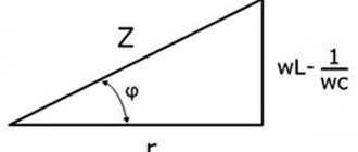
Reactive internal resistance
In addition to galvanic and electrolytic two-terminal networks, there are power supplies whose circuits include reactive elements. When determining their internal resistance, the complex amplitude method is used. It involves using the complex resistances of the elements included in the circuit in calculations. The values of currents and voltages are replaced by the values of their complex amplitudes. The calculation algorithm itself is the same as when calculating active resistance.
The process of measuring r-reactance is slightly different from measuring the active component of resistance. The methods depend on what parameters of this complex function need to be learned: individual components or a complex number.
These parameters are affected by frequency, therefore, in order to obtain information about the internal reactive value r during testing, it is necessary to remove the frequency dependence. This is achieved by a set of measurements over the entire frequency range generated by such a two-terminal network.
Inductor
An inductor is a device whose main part is a conductive metal twisted into a kind of ring or wrapped around a dielectric core. If an electric current passes through such a device, a local magnetic field is formed. This occurs due to the concentration of the alternating magnetic field.
For computer technology, a choke is used, which is used to power various high-precision equipment. The device is required to reduce alternating voltage fluctuations. As frequency is added, the resistance increases accordingly. The technical parameters of the inductor depend on the cross-sectional area of the conductive material and the number of turns around the dielectric core.
Inductor
Calculation
Before studying computing technologies, it is necessary to clarify the basic definitions:
- branches are called circuits with one current;
- nodes are the places where they connect;
- circuits are closed paths for the passage of currents along several branches.
Two postulates should be noted separately. They received the specific name “Kirchhoff’s rules (laws)” after the name of the scientist who formulated the basic principles.
The first law (I1 + I2 + … + In = 0) defines equal to zero the total value of all currents that enter and exit from one point at the junction of several branches.
It must be emphasized! This expression is accurate for any combination of components included in the corresponding circuits (resistors, current sources, and others). For convenience and clarity of calculations, currents entering the node are taken into account with a positive sign, and currents leaving - with a negative sign.
The second rule is mentioned as an intermediate conclusion when considering series-connected resistors (Uip = U1 + U2 + U3). In its classical formulation, the law states the equality of the total EMF of power sources and potentials on passive elements combined in one design circuit.
Series connection of resistors
Taking into account the definitions made, you can create a formula for any number of resistors installed in a single circuit without branches:
Rtot = R1 + R2 + … + Rn.
Regardless of other external components, the input and output currents will be the same in accordance with Kirchhoff's first rule.
Example:
- Uip = 6.5V;
- R1= 8 Ohm;
- R2 = 12 Ohm;
- R3 = 4 Ohm;
- Rtot = 8 + 12 + 4 = 24 Ohm;
- I = 6.5/24 = 0.27 A;
- U1 = I * R1 = 0.27 * 8 = 2.16 V;
- U2 = 0.27 * 12 = 3.24 V;
- U3 = 0.27 * 4 = 1.08 V.
To check a serial connection, a formula based on Kirchhoff's second rule comes in handy:
Uip = 2.16 + 3.24 +1.08 ≈ 6.5 V.
The calculation confirmed the absence of errors.
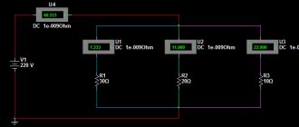
Parallel connection of resistors
In this embodiment, the currents are separated at the input and connected at the output (Kirchhoff's first law). The direction of movement is set from the positive terminal to the negative terminal of the connected power source. In accordance with the rules discussed above, if the voltages on individual resistors are equal, the currents in the corresponding circuits will be different.
For example, you can use the previous source data:
The total resistance in a parallel connection is the formula for the three components:
Rtot = R1*R2*R3/(R1*R2 + R2*R3 + R1*R3
- by inserting the values, make the calculation Rtot = 8 * 12 * 4 / (8*12 + 12*4 +8*4) = 2.182 Ohm;
- I = 6.5/ 2.182 ≈ 2.98 A;
- I1 = 6.5/ 8 = 0.8125 A;
- I2 = 6.5/12 ≈ 0.5417 A;
- I3 = 6.5/4 = 1.625.
As in the previous case, the calculation is checked. If parallel resistance is used, the calculation formula should confirm the equality of the currents:
I = 0.8125 + 0.5417 + 1.6225 = 2.9767 ≈ 2.98 A.
The total equality of input and output values for a single node is maintained, so there are no errors.
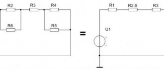
Mixed connection of resistors
If the circuit contains a combination of serial and parallel connections, simplification is performed sequentially using the presented calculation methods.
Sequential circuit conversion for simplified calculations
The following figure shows the sequence of transformations:
- Based on the values of the established R3 and R4, the total value for the chain section Re is determined;
- then calculate the resistance of the series components Re and R6;
- at the next stage, a calculation is made for the group R2, Rek and R5;
- the final action is the summation of R1, Re and R7 (Fig. below).
The final result (Rek) will determine the total (equivalent) electrical resistance of the group of resistors. If necessary, calculate the values of currents and voltages in individual branches.
Series connection of resistances
A serial connection is characterized by the fact that the elements follow each other. The end of one is connected to the beginning of the other. When the resulting chain is connected to a current source, a ring is obtained.
Incandescent lamps connected in series can be considered as resistances
Theoretical part
A series connection is characterized by the fact that the same current flows through all elements. That is, if a chain consists of two resistors R1 and R2 (as in the figure below), then the current flowing through each of them and any other part of the chain will be the same (I = I1 = I2).
Series connected resistances. I1 - current flowing through resistor R1, I2 - current flowing through resistor R2
The total resistance of the entire chain of series-connected resistors is calculated as the sum of the resistances of all its elements. That is, the denominations add up.
Another property of a series connection is that the voltage on each element is different. The current in the circuit is the same, but the voltage across the resistor depends on its value.
Calculation examples
Let's look at an example. The circuit is shown in the figure above. There is a current source and two resistances. Let R1 = 1.2 kOhm, R2 = 800 Ohm, and the current in the circuit is 2 A. According to Ohm’s law, U = I * R. We substitute our values:
- U1 = R1 * I = 1200 Ohm * 2 A = 2400 V;
- U2 = R2 * I = 800 Ohm * 2A = 1600 V.
The total voltage of the circuit is calculated as the sum of the voltages across the resistors: U = U1 + U2 = 2400 V + 1600 V = 4000 V.
This makes it clearer what a serial connection is
The resulting figure can be verified. To do this, find the total resistance of the circuit and multiply it by the current. R = R1 + R2 = 1200 Ohm + 800 Ohm = 2000 Ohm. If we substitute voltage into the formula for a series connection of resistances, we get: U = R * I = 2000 Ohm * 2 A = 4000 V. We find that the total voltage of this circuit is 4000 V.
Now look at the diagram. On the first voltmeter (near resistor R1) the readings will be 2400 V, on the second - 1600 V. In this case, the voltage of the power source is 4000 V.
Ideal EMF source
We have an EMF source
Let's remember what EMF is. EMF is something that creates an electric current. If we connect any load to such a voltage source (even a billion halogen lamps connected in parallel), it will still produce the same voltage as it would have produced if we had not connected any load at all.
Or simpler:
In short, no matter how much current passes through the resistor circuit, the voltage at the ends of the EMF source will always be the same. Such an EMF source is called an ideal EMF source .
But as you know, nothing is ideal in our world. That is, if our battery had an ideal source of EMF, then the voltage at the battery terminals would never sag. But it sags, and the more, the more current the load consumes. Something is wrong here. But why does this happen?
What does the resistance of a resistor depend on?
Temperature and switching sequence are the two main factors that determine the resistance in a circuit. But in addition to these indicators, there are also tolerances. How to measure? In most electrical or electronic circuits, a large 20% tolerance on the same resistor is generally not a problem, but if high precision circuits such as filters, oscillators or amplifiers etc. require low tolerance resistors , then a resistor with the correct tolerance must be used. Since a 20% tolerance resistor cannot usually be used to replace a 2% or even 1% tolerance type.
The five- and six-band resistor color code is most often associated with the high-precision 1% and 2% film types, while the general purpose 5% and 10% garden varieties typically use the four-band resistor color code. Resistors have different tolerances, but the most common are E12 and E24.
The E12 series comes in twelve resistance values per decade (a decade representing multiples of 10, i.e. 10, 100, 1000, etc.), while the E24 series comes in twenty-four values per decade and the E96 series ninety-six values for a decade. The very high precision E192 series is now available with tolerances down to ±0.1%, giving a massive 192 individual resistor values per decade.
How does it depend on temperature?
The higher the temperature, the higher the resistance. This is due to the fast speed of movement of atoms inside a solid. The opposite phenomenon is superconductivity at low temperatures. Again, do not forget about the error.
From other parameters
If a resistor is connected to a complex circuit with many converting, protective, transformation, compression devices, then it will have a different resistance than the standard one, since part of the voltage will still pass through it in an uncompressed form, which will not allow it to work properly . To more accurately determine the specific current and resistance, the indicator obtained in the calculations must be reduced or increased by a given amount.
Electrical resistivity
Resistivity is a parameter that determines the level of obstruction to the movement of electric current through a conductor of a certain length. Depends on the parameter of a particular substance, on the length. For a material with homogeneous properties and a known resistance value and conductor length, the specific parameter is calculated using the formula below.
Calculation of volumetric electrical resistivity
In fact, the meaning of the equation is as follows. Specific resistance is the amount of resistance when passing through a conductor of a certain length, with the same cross-sectional area throughout the entire route.
The parameter is measured in Ohm*meter. Thus, one Ohm*meter is equal to the level of obstacle to the directed movement of charged particles through a homogeneous conducting medium with a length of 100 cm and a cross-sectional area of 1 square meter.
Method - equivalent resistance
The equivalent resistance method is used to calculate electrical circuits in which there are passive elements connected to each other in series, parallel or in a mixed circuit.
For which networks is the equivalent resistance method used?
For example, to use the equivalent resistance method with a large number of equivalent lines, they can be found not based on the results of calculations of flow distribution in each specific network, as was shown in paragraph 9.7, but on the basis of regression dependencies.
How are electricity losses determined by the equivalent resistance method?
| To the calculation of an electrical circuit using the superposition method. |
Each particular circuit is calculated separately, for example, using the equivalent resistance method. The current in a given branch of the original circuit is determined by the algebraic sum of the partial currents of this branch.
Approximate values of H are plotted on the diagram above the risers. Using the equivalent resistance method, this calculation can be performed somewhat faster.
| Circuit diagram with mixed resistance connection. |
Let all the resistances and voltage at the input of this circuit be given and it is necessary to determine the currents of its individual sections. For the calculation, we will use the equivalent resistance method, according to which individual sections of the circuit are simplified and, by gradually transforming them, the circuit is brought to one common (input) resistance. To simplify the circuit, individual groups of series or parallel connected resistances are replaced with one equivalent resistance.
| To the method of equivalent resistances. |
In more complex circuits, the equivalent resistance method achieves a simplification that greatly simplifies the calculation.
| Diagram of flow lines during gas filtration to horizontal. |
In the second method, the true filtration area is replaced by an area with a hyperbolic change in the thickness of the formation h ( R) in the interval Rc h ( R) RK. In this work, to determine the productivity of horizontal wells, the equivalent resistance method is used, which replaces the spatial problem of gas filtration with a flat one. Below are the final calculation formulas obtained using the equivalent resistance method to determine the productivity of horizontal gas wells.
| Replacement of resistors - 2 - 3. Replacement.| Branched circuit with one power source. |
In the diagram Fig. 2 - 1 shows an example of an electrical circuit with one power source and a mixed connection of resistances. The distribution of currents in it at a given voltage and resistance of sections can be determined by the method of equivalent resistances. To do this, individual sections of the circuit are simplified and, by gradual transformation, they are brought to one common equivalent resistance.
Practical tasks:
- Work progress: 1) Connect the laboratory power supply (hereinafter, PSU) to the voltmeter (figure below). Using the regulator knob (located on the power supply), change the voltage on the voltmeter until it shows a value of 9 Volts. Since the internal resistance of the power supply is small (2) Assemble an electrical circuit consisting of an EMF source (laboratory power supply), a variable resistor, a constant resistor R, a voltmeter (multimeter in voltage measurement mode) and key K (open) according to the following diagram: 3 ) Using a variable resistor, set the internal resistance of the EMF source. To do this, take another multimeter and set it to resistance measurement mode. Connect its probes to the variable resistor r. Now, set the resistor resistance: A) 0 Ohm - internal resistance is equal to the resistance of the power supply B) 30 Ohm - internal resistance is approximately equal to the resistance of the crown battery. B) 100 Ohms - the internal resistance of a rather poor source. After setting the resistance for each of options A), B), C), you must turn off the multimeter used to measure the resistance. 4) Next, you need to: Close the key K. Using a voltmeter, measure the voltage drop across the resistor R for cases A, B and C. Analyze the results obtained, based on the measurements, draw a conclusion about the internal resistance of the power supplies. 5)Take photos and post the assembly steps. 6) Fill out the table of voltage drops for cases A, B, C.
- Work progress: 1) Assemble an electrical circuit consisting of an EMF source, two series-connected resistors R1, R2 and a voltmeter (multimeter in voltage measurement mode) according to the diagram: As an EMF source, take a laboratory power supply unit (set to 15 volts). Use resistors R1 and R2 with resistances: A) 1KOhm, 1KOhm. B) 1KOhm, 2KOhm. B) 1KOhm, 5KOhm. D) 1KOhm, 10KOhm. 2) For all options A-D, use a multimeter to measure the voltage drop in section C-B. Analyze your results. In what ratios do resistors share voltage?
Laboratory work Technology+Business
Radio amateur
Good afternoon, dear radio amateurs! Welcome to the website “Amateur Radio”
The formulas form the skeleton of the science of electronics. Instead of dumping a whole bunch of radio elements on the table and then reconnecting them together, trying to figure out what will be born as a result, experienced specialists immediately build new circuits based on known mathematical and physical laws. It is the formulas that help determine the specific values of the ratings of electronic components and operating parameters of circuits.
It is just as effective to use formulas to modernize ready-made circuits. For example, in order to select the correct resistor in a circuit with a light bulb, you can apply the basic Ohm’s law for direct current (you can read about it in the section “Relationships of Ohm’s Law” immediately after our lyrical introduction). The light bulb can thus be made to shine more brightly or, conversely, dimmed.
This chapter will present many basic physics formulas that sooner or later you will encounter while working in electronics. Some of them have been known for centuries, but we still continue to use them successfully, as will our grandchildren.
Ohm's law relations
Ohm's Law is the relationship between voltage, current, resistance and power. All derived formulas for calculating each of these values are presented in the table:
| Required quantity | Formula |
| Voltage, V | U=I*R |
| Current, A | I=U/R |
| Resistance, Ohm | R=U/I |
| Power, W | P=U*I |
This table uses the following generally accepted designations for physical quantities:
U - voltage (V),
I - current (A),
P - power (W),
R - resistance (Ohm),
Let's practice using the following example: let's say we need to find the power of the circuit. It is known that the voltage at its terminals is 100 V, and the current is 10 A. Then the power, according to Ohm’s law, will be equal to 100 x 10 = 1000 W. The obtained value can be used to calculate, say, the fuse rating that needs to be entered into the device, or, for example, to estimate the electricity bill that an electrician from the housing office will personally bring to you at the end of the month.
Here's another example: let's say we need to find out the value of the resistor in a circuit with a light bulb, if we know what current we want to pass through this circuit. According to Ohm's law, the current is equal to:
I=U/R
A circuit consisting of a light bulb, a resistor and a power source (battery) is shown in the figure. Using the above formula, even a schoolchild can calculate the required resistance.
What is what in this formula? Let's take a closer look at the variables.
> U supply (sometimes also written as V or E): supply voltage. Due to the fact that when current passes through the light bulb, some voltage drops across it, the magnitude of this drop (usually the operating voltage of the light bulb, in our case 3.5 V) must be subtracted from the voltage of the power source. For example, if Upit = 12 V, then U = 8.5 V, provided that 3.5 V drops across the light bulb.
> I : current (measured in amperes) that is planned to flow through the light bulb. In our case - 50 mA. Since the current in the formula is indicated in amperes, 50 milliamps is only a small part of it: 0.050 A.
> R : desired resistance of the current limiting resistor, in ohms.
In continuation, you can put real numbers in the formula for calculating resistance instead of U, I and R:
R = U/I = 8.5 V / 0.050 A = 170 Ohm
Resistance calculations
Calculating the resistance of one resistor in a simple circuit is quite simple. However, as other resistors are added to it, either in parallel or in series, the overall resistance of the circuit also changes. The total resistance of several resistors connected in series is equal to the sum of the individual resistances of each of them. For a parallel connection, everything is a little more complicated.
Why do you need to pay attention to the way components are connected to each other? There are several reasons for this.
> Resistor resistances are only a certain fixed range of values. In some circuits, the resistance value must be calculated accurately, but since a resistor of exactly this value may not exist at all, several elements must be connected in series or in parallel.
> Resistors are not the only components that have resistance. For example, the turns of an electric motor winding also have some resistance to current. In many practical problems, it is necessary to calculate the total resistance of the entire circuit.
Calculation of the resistance of series resistors
The formula for calculating the total resistance of resistors connected in series is indecently simple. You just need to add up all the resistances:
Rtotal = Rl + R2 + R3 + … (as many times as there are elements)
In this case, the values Rl, R2, R3 and so on are the resistances of individual resistors or other circuit components, and Rtotal is the resulting value.
So, for example, if there is a circuit of two resistors connected in series with values of 1.2 and 2.2 kOhm, then the total resistance of this section of the circuit will be equal to 3.4 kOhm.
Calculation of the resistance of parallel resistors
Things get a little more complicated if you need to calculate the resistance of a circuit consisting of parallel resistors. The formula takes the form:
R total = R1 * R2 / (R1 + R2)
where R1 and R2 are the resistances of individual resistors or other circuit elements, and Rtot is the resulting value. So, if we take the same resistors with values of 1.2 and 2.2 kOhm, but connected in parallel, we get
776,47 = 2640000 / 3400
To calculate the resulting resistance of an electrical circuit of three or more resistors, use the following formula:
Here again the values Rl, R2, R3 and so on are the resistances of individual resistors, and Rtotal is the total value.
Capacity calculations
The formulas given above are also valid for calculating capacities, only exactly the opposite. Just like resistors, they can be extended to cover any number of components in a circuit.
Calculation of the capacitance of parallel capacitors
If you need to calculate the capacitance of a circuit consisting of parallel capacitors, you simply need to add their values:
Commun = CI + C2 + SZ + ...
In this formula, CI, C2 and SZ are the capacitances of individual capacitors, and Ctot is a summing value.
Calculation of the capacitance of series capacitors
To calculate the total capacitance of a pair of capacitors connected in series, the following formula is used:
Commun = C1 * C2 /( C1 + C2)
where C1 and C2 are the capacitance values of each capacitor, and Ctot is the total capacitance of the circuit
Calculation of the capacitance of three or more series-connected capacitors
Are there capacitors in the circuit? A lot of? It's okay: even if they are all connected in series, you can always find the resulting capacitance of this circuit:
And here again the values C1, C2, SZ and so on are the capacitances of individual capacitors, and Total. — total value.
So why connect several capacitors in series at once when one could suffice? One of the logical explanations for this fact is the need to obtain a specific value for the circuit capacitance, which has no analogue in the standard series of ratings. Sometimes you have to go down a more thorny path, especially in sensitive circuits such as radio receivers.
Calculation of energy equations
The most widely used unit of energy measurement in practice is kilowatt-hours or, in the case of electronics, watt-hours. You can calculate the energy expended by the circuit by knowing the length of time during which the device is turned on. The formula for calculation is:
watt hours = P x T
In this formula, the letter P denotes power consumption, expressed in watts, and T is the operating time in hours. In physics, it is customary to express the amount of energy expended in watt-seconds, or Joules. To calculate energy in these units, watt-hours are divided by 3600.
Calculation of constant capacitance of an RC circuit
Electronic circuits often use RC circuits to provide time delays or lengthen pulse signals. The simplest circuits consist of just a resistor and a capacitor (hence the origin of the term RC circuit).
The operating principle of an RC circuit is that a charged capacitor is discharged through a resistor not instantly, but over a certain period of time. The greater the resistance of the resistor and/or capacitor, the longer the capacitance will take to discharge. Circuit designers very often use RC circuits to create simple timers and oscillators or alter waveforms.
How can you calculate the time constant of an RC circuit? Since this circuit consists of a resistor and a capacitor, the resistance and capacitance values are used in the equation. Typical capacitors have a capacitance on the order of microfarads or even less, and the system units are farads, so the formula operates in fractional numbers.
T=RC
In this equation, T stands for time in seconds, R stands for resistance in ohms, and C stands for capacitance in farads.
Let, for example, have a 2000 ohm resistor connected to a 0.1 µF capacitor. The time constant of this chain will be equal to 0.002 s, or 2 ms.
In order to make it easier for you at first to convert ultra-small units of capacitance into farads, we have compiled a table:
| Capacitance value, µF | Capacitor capacity for calculation |
| 10 | 0,000 01 |
| 1 | 0,000 001 |
| 0,1 | 0,000 000 1 |
| 0,01 | 0,000 000 01 |
Frequency and wavelength calculations
The frequency of a signal is a quantity inversely proportional to its wavelength, as will be seen from the formulas below. These formulas are especially useful when working with radio electronics, for example, for estimating the length of a piece of wire that is planned to be used as an antenna. In all of the following formulas, wavelength is expressed in meters and frequency in kilohertz.
Signal frequency calculation
Suppose you want to study electronics in order to build your own transceiver and chat with similar enthusiasts from another part of the world on an amateur radio network. The frequencies of radio waves and their length stand side by side in the formulas. In amateur radio networks you can often hear statements that the operator works on such and such a wavelength. Here's how to calculate the frequency of a radio signal given the wavelength:
Frequency = 300000 / wavelength
The wavelength in this formula is expressed in millimeters, and not in feet, arshins or parrots. The frequency is given in megahertz.
Signal wavelength calculation
The same formula can be used to calculate the wavelength of a radio signal if its frequency is known:
Wavelength = 300000 / Frequency
The result will be expressed in millimeters, and the signal frequency is indicated in megahertz.
Let's give an example of a calculation. Let a radio amateur communicate with his friend on a frequency of 50 MHz (50 million cycles per second). Substituting these numbers into the above formula, we get:
6000 millimeters = 300000 / 50 MHz
However, more often they use system units of length - meters, so to complete the calculation we just need to convert the wavelength into a more understandable value. Since there are 1000 millimeters in 1 meter, the result is 6 m. It turns out that the radio amateur tuned his radio station to a wavelength of 6 meters. Cool!
Basic Concepts
Electric current flows when a closed circuit allows electrons to move from a high potential to a lower potential in a circuit. In other words, current requires a source of electrons that has the energy to set them in motion, as well as a point for their return of negative charges, which is characterized by their deficiency. As a physical phenomenon, current in a circuit is characterized by three fundamental quantities:
- voltage;
- current strength;
- the resistance of the conductor through which electrons move.
Strength and tension
Current (I, measured in Amperes) is the volume of electrons (charge) moving through a location in a circuit per unit time. In other words, the measurement of I is the determination of the number of electrons in motion
It is important to understand that the term refers only to movement: static charges, for example, on the terminals of an unconnected battery, have no measurable value I. Current that flows in one direction is called direct current (DC), while current that periodically changes direction is called alternating current (AC).
Stress can be illustrated by a phenomenon called pressure, or the difference in potential energy of objects under the influence of gravity. In order to create this imbalance, it is necessary to first expend energy, which will be realized in movement under appropriate circumstances. For example, when a load falls from a height, the work of lifting it is realized; in galvanic batteries, the potential difference at the terminals is formed due to the conversion of chemical energy; in generators, as a result of the influence of an electromagnetic field.
Conductor resistance
No matter how good an ordinary conductor is, it will never allow electrons to pass through without some resistance to their movement. You can think of resistance as analogous to mechanical friction, although the comparison is not perfect. When current flows through a conductor, some potential difference is converted into heat, so there will always be a voltage drop across the resistor. Electric heaters, hair dryers and other similar devices are designed solely to dissipate electrical energy in the form of heat.
In simple terms, resistance (denoted as R) is a measure of how much the flow of electrons is inhibited in a circuit. It is measured in Ohms. The conductivity of a resistor or other element is determined by two properties:
- geometry;
- material.
Shape is of the utmost importance, as is evident from the hydraulic analogy: pushing water through a long, narrow pipe is much more difficult than through a short, wide one. Materials play a decisive role. For example, electrons can flow freely in copper wire, but are unable to flow at all through insulators such as rubber, regardless of their shape. In addition to geometry and material, there are other factors that affect conductivity.
Conductor resistance
So why not apply all these properties to a conductor as well? The thinner and longer the conductor, the greater its resistance to electric current. The material from which it is made also plays an important role .
Therefore, the final formula will take the form
conductor resistance formula
In technology, the outdated unit of measurement of resistivity Ohm × mm2 /m is still used. To convert to Ohm × m, just multiply by 10-6, since 1 mm2 = 10-6 m2.
resistivity of substances
As you can see from the table above, silver has the lowest resistivity, so a silver wire will be the best conductor. Well, the most common and cheapest conductors are copper and aluminum. It is these two metals that are mainly used in the entire electronics and electrical industry.
Substances that offer the least resistance to electric current and have very little resistance are called conductors , and substances that have very high resistance to electric current and almost do not allow it to pass through themselves are called dielectrics . Between them stands the class of semiconductors .
Parallel connection of resistors.
With a parallel connection, the voltages on the conductors are equal to:
U_1 = U_2 = U
And for currents the following expression is valid:
I = I_1 + I_2
That is, the total current branches into two components, and its value is equal to the sum of all components. According to Ohm's law:
I_1 = \frac{U_1}{R_1} = \frac{U}{R_1} I_2 = \frac{U_2}{R_2} = \frac{U}{R_2}
Let's substitute these expressions into the formula for the total current:
I = \frac{U}{R_1} + \frac{U}{R_2} = U\medspace (\frac{1}{R1} + \frac{1}{R2})
And according to Ohm's law, the current is:
I = \frac{U}{R_0}
We equate these expressions and get the formula for the total resistance of the circuit:
\frac{1}{R_0} = \frac{1}{R_1} + \frac{1}{R_2}
This formula can be written slightly differently:
R_0 = \frac{R_1R_2}{R_1 + R_2}
Thus, when connecting conductors in parallel, the reciprocal of the total resistance of the circuit is equal to the sum of the reciprocals of the resistances of parallel-connected conductors.
A similar situation will be observed with a larger number of conductors connected in parallel:
\frac{1}{R_0} = \frac{1}{R_1} + \frac{1}{R_2} + \frac{1}{R_3} + \frac{1}{R_4} + \frac{1} {R_5} + \frac{1}{R_6}
Case Study
The tester is connected in series with the light source. Lighting fixture voltage = 220 Volts. Power unknown. The ammeter reading shows 276 milliamps of current. What is the size of the lamp coil when resistors are connected in series to the circuit?
Formula for finding spiral resistance
Electrical resistance is a physical quantity that corresponds to the degree to which each material obstructs the movement of electrical particles. It is possible to measure the level of a value with a multimeter. In this case, you will have to find the value using the formula. To prevent electrical current from reaching unintended areas, it is advisable to ground the transmission lines. This physical quantity is used in many radio components, for example, LEDs. In an electrical circuit, to find out the value, you need to connect phase and zero to a voltmeter at a known current strength, then calculate it using Ohm's law.
How to find the resistance of a resistor in a circuit
The resistor color code system is good, but we need to understand how to apply it to get the correct resistor value. The "left" or most significant color stripe is the stripe closest to the connection pin, the color coded stripes are read from left to right as follows:
Digit, digit, multiplier = color, color x 10 colors in ohms (Ω)
For example, a resistor has the following marking schemes;
Yellow Purple Red = 4 7 2 = 4 7 x 10 2 = 4700 ohms or 4 kohms ohms.
Typical resistor tolerances for film resistors range from 1% to 10%, while tolerances for carbon resistors range up to 20%. Resistors with tolerances below 2% are called precision resistors, while resistors with lower tolerances are more expensive. The tension itself plays a small role.
Most five-band resistors are precision resistors with 1% or 2% tolerances, while most four-band resistors have 5%, 10%, and 20% tolerances. The color code used to indicate the nominal tolerance of a resistor is:
Brown = 1%, Red = 2%, Gold = 5%, Silver = 10%
For serial connection
The total resistance of the circuit when connected in series in an electrical circuit is equal to the sum of the resistances of individual conductors (or individual sections of the circuit): R = R 1 + R 2.
Can there be errors and what kind?
If the resistor does not have a fourth tolerance band, then the default tolerance will be indicated as 20%. The rest of the current will be dissipated.
The resulting mnemonic maps the first letter of each word to each color, which makes up the color code of the resistors in order of increasing magnitude, and there are many different mnemonic phrases that can be used. However, these sayings are often very crude, but still effective in remembering resistor colors while still helping to determine the resistance.
Error table for more accurate determination of resistance
| Tolerance codes for resistors (±) |
| B = 0.1% |
| C = 0.25% |
| D = 0.5% |
| F = 1% |
| G = 2% |
| J = 5% |
| K = 10% |
| M = 20% |
Also, when reading these written codes, be careful not to confuse the resistance letter k for kilograms with the tolerance letter K for 10% tolerance or the resistance letter M for megohms with the tolerance letter M for 20% tolerance.
Serial connection
Let's start with a serial connection.
According to this scheme, each resistor is connected to another only at one point; there can be 2, 3 or more of them in the circuit. Let us denote the resistances: R1, R2, R3 and the source voltage in the circuit Uts. When a power source is connected, current Ic will begin to flow in it. In a series circuit, current flows through all the resistors one after the other. Since current flows through all resistors of their resistance and the current is summed up, Its = I1+I2+I3, Rts = R1 +R2 + R3, the greater the individual resistance, the harder it is for electrons to overcome a section of the circuit. The power of resistors for series and parallel connections is calculated using different formulas. In series circuits we add it up, in parallel circuits it is an inversely proportional quantity.
A serial connection is characterized by the fact that the elements follow each other. The end of one is connected to the beginning of the other. When the resulting chain is connected to a current source, a ring is obtained.
Theoretical part
A series connection is characterized by the fact that the same current flows through all elements. That is, if a chain consists of two resistors R1 and R2 (as in the figure below), then the current flowing through each of them and any other part of the chain will be the same (I = I1 = I2). The total resistance of the entire chain of series-connected resistors is calculated as the sum of the resistances of all its elements. That is, the denominations add up. R = R1 + R2 - this is the formula for calculating resistance when connecting resistors in series. If there are more than two elements, there will simply be more terms. Another property of a series connection is that the voltage on each element is different. The current in the circuit is the same, but the voltage across the resistor depends on its value.
Serial connection.
Calculation examples
Let's look at an example. The circuit is shown in the figure above. There is a current source and two resistances. Let R1 = 1.2 kOhm, R2 = 800 Ohm, and the current in the circuit is 2 A. According to Ohm’s law, U = I * R. We substitute our values:
- U1 = R1 * I = 1200 Ohm * 2 A = 2400 V;
- U2 = R2 * I = 800 Ohm * 2A = 1600 V.
The total voltage of the circuit is calculated as the sum of the voltages across the resistors: U = U1 + U2 = 2400 V + 1600 V = 4000 V. The resulting figure can be checked.
To do this, find the total resistance of the circuit and multiply it by the current. R = R1 + R2 = 1200 Ohm + 800 Ohm = 2000 Ohm. If we substitute voltage into the formula for a series connection of resistances, we get: U = R * I = 2000 Ohm * 2 A = 4000 V. We find that the total voltage of this circuit is 4000 V.
Now look at the diagram. On the first voltmeter (near resistor R1) the reading will be 2400 V, on the second - 1600 V. In this case, the voltage of the power source is 4000 V. A series connection is a connection of two or more resistors in the form of a chain in which each individual resistor is connected to another individual resistor at only one point.
Total resistance Rtotal
With this connection, the same electric current passes through all resistors. The more elements there are in a given section of an electrical circuit, the more difficult it is for current to flow through it. Therefore, when resistors are connected in series, their total resistance increases, and it is equal to the sum of all resistances.
Ohm's law for a circuit section
With pebbles in a pipe, everything is clear, but not only does the force with which the flow of water flows through the pipe depend on them, it also depends on the pump with which we pump this water. The harder we pump, the stronger the current. In an electrical circuit, the pump function is performed by a current source.
For example, the source may be a galvanic cell (a conventional battery). A battery works based on chemical reactions inside it. These reactions release energy, which is then transferred to the electrical circuit.
Any source necessarily has poles - “plus” and “minus”. The poles are its extreme positions, essentially the terminals to which the electrical circuit is connected. Actually, the current flows from “+” to “-”.
We already have two quantities on which the electric current in the circuit depends - voltage and resistance. It seems it is time to combine them into law.
The current strength in a section of a circuit is directly proportional to the voltage at its ends and inversely proportional to its resistance.
Mathematically it can be described like this:
| Ohm's law for a circuit section I = U/R I - current strength [A] U - voltage [V] R - resistance [Ohm] |
Voltage is measured in Volts and shows the difference between two points in the circuit: this difference determines how much current will flow - the greater the difference, the higher the voltage and the stronger the current will flow.
Current strength is measured in Amperes, and you can read more about it in our article
Let's solve several problems using Ohm's Law for a section of a circuit.
Task times
Find the current strength in an incandescent light bulb if the floor lamp is connected to a 220 V network and the resistance of the filament is 880 Ohms.
Solution:
Let's take Ohm's law for a section of the circuit:
I = U/R
Let's substitute the values:
I = 220/880 = 0.25 A
Answer: The current passing through the light bulb is 0.25 A
Let's make it more difficult. And we will find the current strength, I know all the parameters for calculating the resistance and voltage.
Problem two
Find the current strength in an incandescent light bulb if the floor lamp is connected to a 220 V network, and the length of the filament is 0.5 m, the cross-sectional area is 0.01 mm^2, and the resistivity of the filament is 1.05 Ohm*mm^2/ m.
Solution:
First, let's find the resistance of the conductor.
R = ρl/S
The area is given in mm^2, and the resistivity also contains mm^2 in dimension.
This means that you can substitute values without converting to SI:
R = 1.05*0.5/0.01 = 52.5 Ohm
Now let's take Ohm's law for a section of the circuit:
I = U/R
Let's substitute the values:
I = 220/52.5 ≃ 4.2 A
Answer: The current passing through the light bulb is approximately 4.2 A
Now let's make it even more complicated! Let's determine the material from which the filament is made.
Problem three
What material is the filament of the light bulb made of, if the table lamp is connected to a 220 V network, the length of the filament is 0.5 m, its cross-sectional area is 0.01 mm^2, and the current in the circuit is 8.8 A
Solution:
Let's take Ohm's law for a section of the circuit and express the resistance from it:
I = U/R
R = U/I
Let's substitute the values and find the resistance of the thread:
R = 220/8.8 = 25 Ohm
Now let’s take the resistance formula and express the resistivity of the material from it:
R = ρl/S
ρ = RS/l
Let's substitute the values and get:
ρ = 25*0.01/0.5 = 0.5 Ohm*mm^2/m
Let's refer to the material resistivity table to find out what material this filament is made of.
Order a TOE solution
- Metrology Electrical measurements
- Pigarev A.Yu. RGZ on electrical engineering and electronics in Multisim
- Theory of linear electrical circuits TLETs - Theory of linear electrical circuits of railway automation, telemechanics and communications: assignment for tests No. 1 and 2 with methodological instructions for fourth-year students of the specialty Automation, telemechanics and communications in railway transport - Test No. 1
- — Test No. 2
- — Electrical engineering and fundamentals of electronics: Guidelines and test assignments for part-time students of engineering and technical specialties of higher educational institutions / Sokolov B.P., Sokolov V.B. – M.: Higher. school, 1985. – 128 p., ill. – Test No. 1 Electric circuits
- — Artemenko Yu.P., Sapozhnikova N.M. Theoretical foundations of electrical engineering: A manual for course work MSTU GA 2009