Projects of all electrical networks are created on the basis of special technical documentation, which displays the design and operational capacities, parameters and characteristics of the electrical network design of the room or building as a whole. All this documentation is regulated “Rules for technical operation of consumer electrical installations”. The rules are developed on the basis of current legislative acts, state standards and other regulatory and technical documents. The technical operation rules take into account proposals from electrical repair organizations and research institutes. The fundamental document in design documents is the power supply diagram.
Why single line?
Single-line and multi-line from GOST
In relation to electrical circuits, the term “single-line” means that the channels for transmitting electricity and signals are depicted as one line, regardless of the actual number of phases.
Let us immediately emphasize that this principle of simplification is used not only for drawing power lines, but also for schematizing multi-wire control harnesses and buses, the number of wires in which can be more than 3.
This approach can significantly increase the information content of the drawing, so today single-line diagrams are the main document around which the rest of the design documentation is grouped.
The general provisions on the basis of which a drawing of a single-line diagram of electrical equipment is developed are specified in GOST 2.702-2011.
According to this document, the basic principle of simplification can be formulated as follows: 2-3-phase electrical wiring channels are represented by one line, and the number of phases corresponds to the number of oblique “notches”.
Individual elements in a phase
In cases where the number of wires in a line is more than three, a number is used instead of notches. If the line is single-phase, no additional markings are required.
It should be noted that the development of a single-line power supply diagram is carried out, first of all, for a comprehensive analysis of the designed power network, therefore, in most cases, such diagrams are made on one sheet.
When developing circuits for large networks, the principle of multi-level detail is applied. That is, the general (complex) diagram reflects the interaction between large structural blocks, and the details of the structural blocks are given on other sheets.
Devices and switching elements connected to each phase of a multi-wire line are represented by one symbol indicating the phases on which this device is installed.
Design stages
Let's consider the main stages of designing a single-line power supply diagram using the example of a private house:
- First of all, you need to obtain specifications (technical specifications) from the company involved in the supply of electricity;
- Obtain permission and master plan from City Architecture. The general plan displays all communications adjacent to the site so as not to damage them during work;
- After this, a power supply plan for the suburban area is directly developed;
- The developed scheme requires final approval by the municipal branch of the energy supply company.
Let's sum it up
In conclusion, we note that now there is no need to draw sketches on paper yourself. For this, there are special programs that, based on the entered data, will produce a finished result within a few minutes. All that remains is to print out the diagram and approve it in the relevant authorities.
Our company’s specialists develop single-line power supply diagrams (executive and settlement) for various enterprises, industrial and private facilities.
Main types of single-line electrical circuits
The development of a single-line diagram is carried out in two cases:
- at the beginning of design (“design diagram”);
- at the operational stage, before upgrading the equipment (“executive single-line diagram”).
The design schematic diagram is the main one and is used as the basis for calculating all technical parameters of the electrical network. For initial approvals, this particular version of the scheme is used.
In practice, the original version of the electrical project is often changed at the stage of electrical installation work or at a later date, before modifications and modernization. To plan and record changes, an executive power supply diagram is drawn up.
Let us remind you that according to the requirements of the PUE, after any change in the power supply network or the design of the electrical installation, the electrical project must be re-approved. In this case, the executive version of a single-line diagram is used as the main technical document.
Design of power supply circuits
If necessary, it is possible to change the sequence of assigning serial numbers depending on the placement of elements in the product, the direction of signal flow or the functional sequence of the process. However, I have found a few that are easy to use for the average person. Functional units or devices, including those made on a separate board, are highlighted with dashed lines. To make better use of the program's capabilities and make better use of time, hager has developed an interface between this new program and the semiolog label program.
Photo - single-line diagram There are two types of such diagrams: Calculated; Executive. Design diagram of an apartment panel of a country house At the stage of operation of the facility, single-line executive diagrams are drawn up, which display all the changes made to the configuration of the electrical network during its use.
It is the single-line power supply diagram of an enterprise, home, or workshop that is the fundamental document according to GOST, which is responsible for the operational responsibilities of different parties. This option is extremely easy to use even for a non-professional, while being functional and effective at the same time.
In this case, positional designations are not assigned to the tables. The length of cables and wires must be displayed to scale with extreme accuracy, and their exact layout must also be shown. It is this document that is necessary for subsequent approvals with the authorities issuing technical conditions for connecting the construction project to existing electrical networks, which are the electrical grid organizations at the location of the electrical energy consumer facility.
Above the table it is allowed to indicate the UGO of the contact - socket or pin. The information listed above must be present on the single-line diagram.
An example of designing a single-line diagram of the power supply of an industrial enterprise. Types of single-line electrical diagrams. Depending on at what stage of the work on creating the electrical network of the facility a single-line diagram is drawn up, its type and direct purpose depend. In accordance with GOST, the finished electrical power supply circuit diagram must have a stamp of the established type. HOW CURRENT FLOWS IN THE CIRCUIT - Read Electrical Diagrams Part 1
What should be shown on a single-line electrical diagram?
Any design option for a single-line diagram of an electrical project must contain the following information:
- boundaries of the areas of responsibility of the energy supply organization and the electricity consumer;
- input distribution devices. If the project uses autonomous generators and automatic transfer switches, they should also be reflected in the diagram;
- electricity meters, with comments on the method of their installation;
- information about all involved distribution cabinets;
- cable line lengths accurate to the nearest meter;
- position and technical parameters of automatic shutdown devices;
- position and technical parameters of the RCD;
- data on all installations consuming electricity indicating power, cos ϕ.
If possible, the mechanical relationship of the elements displayed on the diagram is indicated.
Please note that the symbol of a device or switching device must be accompanied by an additional description revealing its main technical parameters.
There are two ways to post additional information:
- directly next to the element symbol;
- decoding in the specification table.
When using the second method, each element of the circuit must have a unique marker (or number).
The general design of the drawing must comply with the requirements of the ESKD.
Design Features
As already noted, a single-line diagram is used to draw up a plan for the power supply of a private house, apartment or industrial enterprise. There is no need to detail it. The main purpose of such a drawing is to give a general idea of the electrical supply system.
Let's consider what is needed to draw up such a project:
- Calculate the total power of power loads. This parameter is taken by adding the maximum power of each electric current consumer;
- Depending on the power of consumers, select the required cross-section of electrical wiring and general cables. In this case, the section is rounded upward;
- Protective devices are selected in accordance with the calculated loads. It is recommended to install several types of protective devices. An example for an apartment or private house is an RCD and circuit breakers that complement each other;
Based on this, the diagram should display the following elements:
- Connection point. This can be either a transformer substation or a general input into the house (for an apartment);
- Type of input distribution device;
- Brand and type of metering device (electricity meter);
- The length of the cables, as well as their brand, cross-section and number of cores. It is necessary to indicate the method of wiring: open or hidden;
- Consumer groups are indicated. The rated power consumption is indicated for an industrial facility;
- The lighting circuit is indicated, without indicating the light sources.
Important! If there is an autonomous source of power supply in the house, such as a diesel generator, it must also be indicated on the diagram with the circuit breakers and switches included in the circuit.
Regulations
When developing single-line diagrams, it is necessary to take into account that the symbols used must comply with the following regulatory documents:
- wires, contacts, circuit structuring (GOST 2.709-89);
- switching elements (GOST 2.755-87);
- conventional graphic symbols for elements of electrical circuits (sockets, lamps, RCDs, etc. - GOST 2.721-74).
Separately, it is worth noting that the letter designations for elements of single-line electrical circuits are also standardized and defined in GOST 2.710-81.
Despite a fairly extensive set of standardizing documentation, disagreements sometimes arise regarding some types of UGO. One of the reasons for such inconsistencies is the lack of certain symbols in programs for developing electrical circuits.
For an ordinary developer of an electrical project, this fact may cause a refusal at the approval stage, which is why it is recommended to entrust the development of electrical documentation to licensed organizations familiar with the features of technical control during approval by Energosbyt and Rostekhnadzor.
Design principles
Principles of construction
When developing and preparing the drawings included in the OSE, it is necessary to strictly comply with the norms of the PUE (electrical installation rules), as well as the requirements for this type of work indicated in the regulatory documentation. Before starting the process, you need to familiarize yourself with the nomenclature of circuit elements .
What should a single-line power supply diagram include?
The content of the single-line diagram is regulated by regulatory documentation presented to the applicant after consideration of the request for obtaining technical specifications. The design diagrams should indicate :
- the framework of the areas of responsibility of the supplier and consumer of electricity - they are presented in the text of the contract for the provision of services for the supply of premises;
- the main distribution board and consumer-owned transformer stations, indicating automatic transfer switching devices (if any);
- autonomous power supply (if available);
- the distribution cabinets of both lighting equipment and power lines present in the room
- horizontal dimensions of main power lines cables used for communication and how they are laid;
- calculated data on energy losses during transmission ;
- information about emergency operation;
- equipment for electricity metering with the designation of the transformation ratio (if a secondary electric current of 5 A is used);
- technical characteristics of fuses, automatic shutdown devices ;
- information about the loads with notes about their power in kW and current.
A drawing developed taking into account the given data can later be supplemented with additional graphical representations that are not subject to special approval.
Question to the expert
Who approves the project?
Signatures, according to regulatory sources, should be collected from the specialist who developed the scheme, the official who checked it, and the manager who approved the project. The initial approval is approved by the person responsible for the power supply on the consumer’s side, and subsequent approvals are determined by the characteristics of the premises and the work carried out in it.
Design stages
The stages of developing a single-line diagram have a certain sequence. First, the applicant is required to submit a request to the company providing electricity supply services to issue technical specifications for the implementation of this task. After waiting for the documents regulating the process to be received, consumer representatives prepare a draft scheme for these specifications. The developed drawing is agreed upon with the company that issued the technical specifications.
If during the operation of the electrical network there is a need to make changes to the configuration of its elements , an executive diagram . The sequence of stages for it will be identical.
Design rules, GOST requirements
Numbers of state standards:
- 2.721-74 – introduces graphic symbols in diagrams;
- 2.755-87 - describes how to designate switching devices and contact connections;
- 2.709-89 – talks about wire symbols;
- 2.710-81 – signs combining letters and numbers.
Conventions used in drawing up single-line diagrams
The visual representation of the various elements that make up the energy supply system is regulated by regulatory sources. Boxes, panels and cabinets have their own designations in the drawing documents:
- Shields are shown as rectangles. The main shield elements have a horizontal line that cuts off a small fragment at the bottom. Group elements responsible for working lighting are filled with black paint; for emergency lighting, they have two diagonals.
- Single panels and one-way service cabinets are represented by squares with a fragment cut off horizontally at the bottom. Double-sided service elements have cut-offs at the top and bottom. This rule also applies to elements from several panels, only they are presented as the corresponding number of squares arranged in a row.
- The pull-out box has a square shape. The introductory box is represented as a square crossed out by a thick vertical line.
- The branch box is depicted as a circle with a thick transverse line and a vertical line going down from the center of the circle.
A regular switch looks like a circle with a line extending from it to the right and upward. The number of poles (one, two, three) is demonstrated by the number of small vertical lines at its end. If an open installation is assumed, the lines are drawn from the base to the right and down, and in the case of a hidden one , it is intersected by transverse lines. Double and triple elements have two or three lines instead of one. A high degree of protection is demonstrated by painting the circle black. If the element works in two directions , a second line is drawn to the left and down from the circle.
The socket is shown as a “lying” semicircle with a line extending upward from the top. The presence of two poles is described by a second similar feature, the protective contact is an additional horizontal, hidden installation - running from the center to the top. Strong defense is shown by shading in black.
Designation of lighting fixtures
Designations of lighting devices :
- Lamps with fluorescent lamps are shown as elongated rectangles, other devices are shown as circles.
- The cable is depicted with a transverse dotted line and a thick line under it near the “equator” of the circle.
- External lighting devices are shown with the letter “T” turned on its side, growing from the left side of the circle.
- The chandelier is shown by dividing the circle into 6 segments.
- The lamp wall socket is a blackened triangle with a V-shaped fork on top.
- The suspended cartridge is a circle crossed out by diagonals. Ceiling - similar, but the crossing out elements located within the figure are not applied to the image.
- Ammeter, voltmeter, galvanometer are round shapes with the letters A, V and an upward arrow inside, respectively.
- Temperature sensor and oscilloscope – squares. The first has a t inside and an arrow pointing to the right that coincides with the base. The second one has a thin N-shaped image of a lightning bolt.
- The electricity meter is a tall rectangle with a separated upper segment and the inscription Wh.
If the circuit designer has any doubts about how to depict a particular element, he can familiarize himself with the nomenclature of OSE symbols in the reference literature.
Some features of generalized electrical circuits
As mentioned above, drawing up a single-line power supply diagram is the main stage in developing an electrical project for a house. In addition to the technical data of the elements, such diagrams also indicate the following type of information:
- additional operating modes (for example, about the emergency operation mode of the ATS);
- calculation of losses in power transmission circuits;
- division of the network by type (backbone, group, distribution).
A single-line diagram developed taking into account the above requirements can later be supplemented with other drawings that do not require separate approval.
Definition
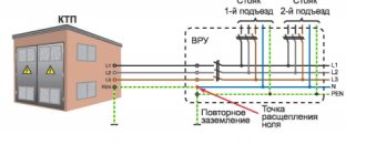
As the name suggests, a single line diagram is a graphical representation of a two- or three-phase network that connects all devices in an electrical circuit using a single line. This allows you to significantly simplify technical documentation, making it less voluminous and more understandable. Let's give an example that shows a simple single-line diagram.
As you can see, the example displays a two-phase circuit into which various consumers of a private house are connected.
To display a single-line three-phase network, several notations are used:
- Three oblique segments located at the load input;
- One oblique line with the number 3.
Note! All electrical devices and other network elements have their own designations approved by certain GOSTs.
Who checks and approves
According to regulations, a single-line diagram of an electrical project must be signed by the following employees:
- developer;
- inspector;
- approving manager.
The further procedure for approvals depends on the specifics of the project, but the first approval is endorsed by the person responsible for electrical equipment on the consumer’s side.
The Mega.ru campaign is a licensed developer of electrical documentation and provides professional development of single-line diagrams for buildings and structures that are subject to approval by Moenergosbyt. To clarify the terms of cooperation, please call the numbers published in the “Contacts” section.
Purpose
Why are single-line power supply diagrams developed and compiled? They are necessary for drawing up basic documents, which include contracts for the supply of electricity. Based on a single-line power supply diagram, specialists determine the balance sheet boundary and also delimit the operational responsibilities of the parties. The connection point is used as a demarcation. So, until then, all responsibility lies with the electricity supplier (network owner). Once the connection point has been passed, all problems are on the shoulders of consumers. Commercial metering of supplied electricity is carried out using an input device, which is usually installed at a given location. Typically, homogeneous groups have their own preferences when placing the necessary additions. So, if you look at how a single-line power supply diagram for a private house is constructed, you can see that the calculation device is always located on the street side and close to the electricity supply line.
Characteristics of a single-line diagram
In order for the diagram to meet all the necessary operational conditions and structural features of the building for which it is being drawn up, it is divided into two types: a design single-line diagram and an executive diagram. But still, before considering the distinctive characteristics of such schemes, it is worth highlighting the general requirements that must be implemented when designing them.
What issues need to be addressed?
Despite the simplicity, which is an important advantage, when a single-line power supply diagram is being developed, the following components must be specified:
- Object connection point.
- Balance sheet limit.
- The brand and rated current of the device located at the connection point.
- The brand of the supply cable (overhead line), as well as its length and cross-section.
- Information about the devices with which commercial accounting will be carried out.
- Theoretical voltage losses that will occur in overhead and cable lines.
- Design and installed capacity of the ASU.
- Design loads to which power supply lines will be subjected.
- ATS cabinet, as well as its operating mode.
- Brand and rated current of protective switching equipment.
Now we have reviewed single-line power supply diagrams, symbols and issues that need to be worked out. So you can say that you have the theoretical minimum in a given technical area.
Letter designations
In addition to the fact that the elements on the diagrams have conventional graphic names, they have letter designations, which are also standardized (GOST 7624-55).
| Electrical circuit element name | Letter designation | |
| 1 | Switch, controller, switch | IN |
| 2 | Electric generator | G |
| 3 | Diode | D |
| 4 | Rectifier | VP |
| 5 | Sound alarm (bell, siren) | Sv |
| 6 | Button | Kn |
| 7 | Incandescent lamp | L |
| 8 | Electrical engine | M |
| 9 | Fuse | Etc |
| 10 | Contactor, magnetic starter | TO |
| 11 | Relay | R |
| 12 | Transformer (autotransformer) | Tr |
| 13 | Plug connector | Sh |
| 14 | Electromagnet | Em |
| 15 | Resistor | R |
| 16 | Capacitor | WITH |
| 17 | Inductor | L |
| 18 | Control button | Ku |
| 19 | Terminal switch | Kv |
| 20 | Throttle | dr |
| 21 | Telephone | T |
| 22 | Microphone | Mk |
| 23 | Speaker | Gr |
| 24 | Battery (voltaic cell) | B |
| 25 | Main engine | Dg |
| 26 | Cooling pump motor | Before |
Please note that in most cases Russian letters are used, but the resistor, capacitor and inductor are designated by Latin letters.
There is one subtlety in the designation of the relay. They come in different types and are marked accordingly:
- current relay - RT;
- power - RM;
- voltage - RN;
- time - RV;
- resistance - RS;
- index - RU;
- intermediate - RP;
- gas - RG;
- with time delay - RTV.
Basically, these are only the most conventional symbols in electrical circuits. But you can now understand most of the drawings and plans. If you need to know images of rarer elements, study GOST standards.
