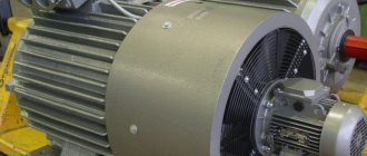
The rotor and stator are the two main components that ensure proper operation of electric motors. Each of them has its own technical features that determine their working potential. Next, we will talk about the features of stators installed in asynchronous motors.
Stator rewinding
AC power units are devices whose main task is to convert electricity, which is supplied as a sinusoidally varying or alternating current, into mechanical rotational energy. This is realized through the relationships between magnetic fields and conductors. Unlike those motors that require direct current to operate, these power units do not require brushes or commutator elements. It is devices of this type that include the options that we will consider today - AC asynchronous electric motors.
These motor models include a stator, which has a winding responsible for generating a rotating magnetic field. Asynchrony consists in the fact that the revolutions of the rotor mechanism are by default slower than the speed of revolutions from the magnetic field. The difference in the speeds of the field and the rotor is known as slip, and the torque indicator is proportional to it. Based on this, the speed of the motors directly depends on the excitation frequencies and the level of applied load.
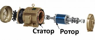
Three-phase asynchronous motors in traditional versions are electrical units that contain two main functional elements: a moving rotor and a stationary stator.
General characteristics of the stator
The motor stator, in turn, includes a frame into which an element such as an electromagnetic core is mounted. Its main task is to include a magnetic drive and a three-phase distributed stator winding. The core is responsible for the magnetization of the unit, as well as for the creation of a magnetic field in constant rotation.
In all types of asynchronous electric motor construction, the stator magnetic wires (cores) are made of layers of electrolytic steel, the thickness of which does not exceed millimeters. If the equipment is of low power, then the layer can have a thickness of 0.65 mm.
All sheets are isolated from each other by one of two methods: varnishing or oxidation. It is also quite common to use steel with an already applied electrical insulating coating.
The magnetic wire provides low magnetic resistance for the flow of magnetic pulses that are generated by the stator windings. Providing magnetization enhances the flux.
Example of a stator magnetic drive
A distributed winding into three phases for the stator is placed in the magnetic grooves. The simplest winding implementations consist of three phase coils, whose axes are shifted relative to each other by a level of 120 degrees. Next, these coils are connected to each other according to two already known schemes: “triangle” or “star”.
Connection of phase windings
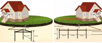
There is another concept that plays an important role in the operation of the stator of an asynchronous motor - the distance between the rotor and stator, the gap. Its value directly affects indicators not only of an energetic nature, but also of vibroacoustic ones. When the gap decreases, the reactive component of the current for engine operation at idle speed also decreases. Based on this, the level of magnetic dispersion and inductive reactance of the power unit increases. In asynchronous electric motors, the gap varies from 0.2 to 2 millimeters.
Modifications for cars
Electromagnetic motors for cars are manufactured only of the commutator type. Their power averages 40 kW. In turn, the rated current parameter is 30 A. The stators in this case are two-pole. Some modifications have a terminal box. Fans are used to cool the system.
The devices also have special openings for air circulation. Rotors in engines are installed with metal cores. Seals are used to protect the shaft. The stator in this case is located in a casing. Electromagnetic motors for machines with solenoid relays are rare. On average, the diameter of the shaft does not exceed 3.5 cm.
Windings
Before we begin to characterize the windings directly on the stator of an electric motor, let's look at what these windings are. They are a set of wire turns, which together form an electrical circuit, which in turn sums up all the electromotive powers induced in these same turns. The coil is the simplest example of such windings, where the turns are sequentially placed next to each other.
Windings are classified into the following groups according to different criteria:
- by method of application - stator and rotor. One of the key classifications;
- according to the method of arrangement in the grooves - two- and single-layer;
- according to the shape of the coils - equal-coil and concentric type;
- by type of frontal parts - two and three stripes, as well as basket (or concentric);
- by type of wire cross-section - hard (consisting of cables with rectangular conductors) and soft (made of round wires).
Many more classifications have been implemented that allow you to select a stator coil according to a certain indicator.
There are also patterned and concentric windings, all of which are single-layer. In the latter case, the winding includes coils, which are located one inside the other.
Example of a concentric winding
The exact number of coil groups is 6p. When the number of pole pairs is even, then the number of coil groups is also indicated as even. At the same time, the first half of such sets are produced with long frontal sections, and the second - with short ones. In situations in which the number is unpaired, one group is realized asymmetrical.
In a concentric winding made of the “waddling” type, groups of coils are classified into two subgroups. Such winding occurs when the q index exceeds 2 and makes it possible to reduce the levels of overhang of the frontal elements due to their more convenient placement.
Sets of coils of asymmetrical design are not used in these types of designs even if there is an even number of pairs of poles. Indicators of electrical resistance when winding cones occur through the same length of the winding components of the coils in phases:
- one phase includes all small subclasses;
- the second – middle level;
- the third is large.
This promotes some changes in the winding. For example, the front winding components of the concentric type are placed in two or three areas at once. Based on this, the windings are of the following types:
- two- or three-plane;
- two- or three-tier.
The above variations occur when the frontal parts are installed on tiers or in planes.
The frontal elements of windings using the “waddling” method are placed in 3 positions at once. These windings are often described as bobbin windings, because they are not always the same due to differences in the length of each individual front part.
Example of waddle winding
Pattern windings are implemented as symmetrical, because the coils have the same dimensions. The simplest among them are template ones, which are shown in the figure below.
Template winding
Next come the standard waddle and chain ones. We looked at their technological features a little higher.
Parallel Excitation Models
Electromagnetic motors of this type are made on the basis of brush commutators. There are no anchors in this case. The shaft in the devices is mounted on roller bearings. Also, special paws are used to reduce the friction force. Some configurations have magnetic cores. Models can only be connected to a DC network.
It is also important to note that the market mainly consists of three-stroke modifications. The brush holders in the devices are made in the form of cylinders. The models differ in power. On average, the operating current at idle does not exceed 50 A. To enhance the electromagnetic field, rotors with high-voltage windings are used. Some configurations use tips on magnetic cores.
Possible losses in an asynchronous motor
Three-phase asynchronous power units during operation encounter the following types of power losses:
- stable or permanent type;
- variables.
Let's look briefly at each of these types.
Permanent (stable) or fixed
Losses of constant presence are those losses, the indicator of which remains at a certain level under the traditional operating mode of an asynchronous power unit. They are easily obtained by testing without load on a three-phase motor. These power losses are classified into 3 main categories:
- loss of “iron” or stator core;
- mechanical type;
- brush friction losses.
Iron and Core Damage
They, in turn, are classified into hysteresis and eddy stress types. In the latter case, their level is minimized by implementing protection on the core. In this case, its area decreases, which in turn contributes to an increase in the level of resistance and a simultaneous decrease in eddy currents.
Hysteresis losses are minimized using high-quality silicon steel. This indicator is directly determined by the frequencies of the voltage supplied to the winding.
The stator frequency in all situations is the feeding frequency (f), and the rotor frequency is the slipping frequency. The last indicator is additionally multiplied by the feed (sf), which always has an indicator less than the stator.
Induction motor core stator
The frequency level on the stator is about 50 hertz, while on the rotor this indicator reaches a level of 1.5 hertz. This is due to the fact that, under normal operating conditions, the phenomenon of slippage is about 3%. These are also determined by the losses of the rotor core, which are comparatively very small if combined with the damage of the stator core. As practice shows, such losses are not significant and are not taken into account during operation.
Mechanical and brush losses
The first phenomenon most often occurs in bearings, and damage due to brush friction occurs only in asynchronous power units with a rotor that includes windings. These losses are zero at the start. As the speed indicator increases, the level of losses increases proportionally. In three-phase motors, the speed indicator in most cases remains at a constant level. Based on this, it can be argued that losses will also remain constant or will have minor differences.
Variables
They are often called copper losses, which is determined by the characteristics of their occurrence. They arise through an electric current that flows through the rotor and stator windings of an asynchronous motor. When the load level changes, the current also changes in parallel, due to which the losses change their indicators. Based on this, the second name for such losses is variables. Getting them is quite simple - you need to carry out a test with a non-working rotor of the power unit for 3 phases.
The main purpose of an asynchronous motor is to convert electrical energy into mechanical action. During this process, energy goes through a variety of stages. When passing through various stages, it is displayed on a special diagram for the flow of energy.
The 3-phase asynchronous unit also has a three-phase supply. It goes directly to the stator of the power unit. In order to accurately calculate the electrical energy input to a static component, it is worth applying the following formula:
Pin = 3*VL*IL*cos
- Pin is a resultant value indicating the level of electricity supplied directly to the stator;
- VL is an indicator of the linear electrical voltage that is supplied to the stator of a 3-phase motor;
- IL – current of similar type;
- Cos is an indicator of the force coefficient of the control unit.
A certain part of the energy is initially used for the purpose of uninterrupted support of the stator, in particular, for losses of “iron” and copper. The energy that is saved (that is, the electricity at the input - stator losses) goes further to the rotating rotor, also to its input.
The input level on the rotor is determined by the following formula - P2 = Pin - losses on the stator. In the latter case, these are also copper and iron losses. In this case, the rotor must convert this supply into mechanical energy. The input itself cannot be converted into the same output, because it must ensure the maintenance of rotor losses.
Electrical losses in the stator winding are determined by their heating during operation. This is due to the currents that pass through them. The connection here is directly proportional - the greater the load on the engine, the greater the damage.
It is important to take into account the diverse losses that occur in the stator windings of asynchronous motors when calculating the rated current level in three-phase devices.
Modifications with wound rotor
The wound rotor electromagnetic motor is installed on machine tools and is often used in heavy industry. In this case, magnetic cores are equipped with armatures. A distinctive feature of the devices is considered to be large shafts. The voltage is directly supplied to the winding through the stator. A brush holder is used to rotate the shaft. Some of them have slip rings installed. It is also important to note that the power of the models is on average 45 kW. The motors can be directly powered only from an alternating current network.
Connection diagrams
The connection of the stator and rotor windings of an electric motor is carried out according to one of two schemes: “star” or “delta”. When using the first scheme, some ends of the stator windings are connected to each other, and the others are supplied with three-phase voltage (380 volts). At the same time, it is worth paying attention that a motor with windings connected in a star method has less power when compared with another method.
Delta connections are implemented by connecting all stator windings in series. That is, each winding is connected at its end to the beginning of the next coil. Switching engine components according to this scheme will provide an order of magnitude greater operating power, as full as possible. At the same time, the starting currents in such a circuit are quite high, which is why it is recommended to use a “star” to start the equipment, and then switch to a “delta” during operation.
Squirrel-cage models
An electromagnetic motor with a squirrel-cage rotor is often installed in household appliances. The average power of the models is 4 kW. The stators themselves are of the two-pole type. The rotors are mounted at the rear of the engine. The models have a small diameter shaft. Today, asynchronous modifications are most often produced.
There are no terminal boxes in the devices. Special pole pieces are used to supply current. The engine circuit also includes magnetic circuits. They are mounted near the stators. It is also important to note that devices are available with and without brush holders. If we consider the first option, then in this case special gears are installed. Thus, the stator is protected from the magnetic field. Devices without a brush holder have a seal. Bendix motors are installed behind the stator. Dowels are used to secure them. The disadvantage of these devices is the rapid wear of the core. It occurs due to increased temperature in the engine.
Operating principle of an asynchronous motor
Using a three-phase stator winding, a magnetic field is created, which rotates at a certain speed during operation. It is defined like this:
n1=60fp
Electromagnetic interaction between the stator (stationary device) and the rotor (moving) occurs only when the rotation speeds of both of these components are not equal. This relationship is expressed by the following formula:
s=n1-nn1
This indicator is also called slip, which we already wrote about in our article. The stator itself operates in several modes, which determines the versatility of the device design.
In asynchronous motors, the frequency of the rotating field created in the air gap and the rotor speed do not coincide. Based on this, electric motors are called asynchronous. The frequency indicator of the rotating field in the air gap depends on the motor supply frequency and the number of poles and does not change depending on the motor load, but the rotor speed varies depending on the load. As the load increases in the engine operating area. In this case, the engine rotation speed decreases, and when the load decreases, the engine rotation speed increases. Engine rotation speed is highest in idle mode. The speed indicator of an asynchronous electric motor in the engine operating environment cannot exceed the rotation speed of the rotating field. The rotation speed of the rotating field is calculated using the following formula:
N = 120xf/P
N – speed of movement of the magnetic field, expressed in revolutions per minute;
f – operating power frequency, measured in hertz;
P – number of poles of the stator winding.
We present a graph of the ratio of torque and speed of an asynchronous electric motor for 3 phases.
Example of a torque-speed graph of a three-phase induction motor (speed and power)
Each asynchronous type electric motor with rotor and stator windings has the following features:
- can be used directly from the mains. In this case, speed adjustment is not possible;
- has the ability to be operated when feeding with a driver responsible for variable speed. The main goal is speed regulation. Motors are excellent for scaling tasks and vector control;
- the same motor can be used in both 50 Hz and 60 Hz networks;
- used for starting according to star and delta circuits, or for soft starting to limit starting currents.
Engine mode
Schematically, this operating mode can be depicted as follows:
Operation in engine mode
As you can see, the figure shows a stator magnetic field that rotates in a clockwise direction. When n exceeds n1, the stator field lines move relative to the rotor, also clockwise, but at speed n1 – n. In physics, the so-called third-hand rule is used, according to which the electromotive force in the rotor conductors under the upper (north) pole is directed in our direction, and the south pole is directed away from us. Active current components in conductor parts also have directions. Electromagnetic type forces for the interaction of stator and rotor magnetic fields in the process create a torque in the forward direction with the stator field.
The speed indicator n, which characterizes the operation of a rotating motor, directly depends on the level of applied load. When operating at idle speed, the speed indicator practically reaches the n1 level, based on the condition that at n1 = 0 the electromotive force and rotor currents also reach zero level. This causes the disappearance of electromagnetic influence.
Based on this, the asynchronous power unit operates in engine mode within limits starting from n = 0 and reaching n ≈ n1. That is, when slip occurs in an electric motor, it varies in the range from s+1 s ≈ 0. The electrical energy that is supplied to the stator from the power supply is converted at the shaft into mechanical energy.
Generator mode
To begin with, let's imagine that a stator is connected to the power supply network, and during operation it creates a rotating magnetic field. The rotor starts and moves in the same direction, the speed of the component is n ˃ n1. Here the slip will be at a negative level, and the EMF (electromotive force) and rotor currents change directions of movement when compared with the previous operating mode of the engine. Meanwhile, the torque on the shaft performs a braking function in relation to the torque of the primary electric motor. The asynchronous power unit acts as a generator. The mechanical energy supplied to the shaft is converted into electrical energy and transmitted further to the electrical network. Thanks to this scheme, the asynchronous motor operates in the mode of an electric generator, in parallel with the power network in the range from n = n1 to n, that is, when the slip varies from s = 0 to s = -∞.
An example of a simple pattern winding when 2р=2
Electromagnetic brake mode
This situation occurs when the rotor begins to rotate in the direction opposite to the rotation of the magnetic flux produced by the stator. Here, electrical energy is supplied from two sides at once:
- from the power supply – electric;
- from the primary power unit - mechanical.
This operating mode represents the functionality of the electromagnetic brake. It occurs in situations where sliding starts from s = +1 to s = +∞.
The most striking example of the practical application of this operating mode is the lowering of loads in cranes and transport devices.
What is a commutator motor?
The length of a DC motor depends on the class. For example, if we are talking about a 400 class engine, then its length will be 40 mm. The difference between commutator electric motors and their brushless counterparts is their ease of manufacture and operation, and therefore their cost will be lower. Their feature is the presence of a brush-commutator unit, with the help of which the rotor circuit is connected to the chains located in the stationary part of the motor. It consists of contacts located on the rotor - a commutator and brushes pressed to it, located outside the rotor.
Rotor
Brushes
These electric motors are used in radio-controlled toys: by applying voltage from a DC source (the same battery) to the contacts of such a motor, the shaft is set in motion. And to change its direction of rotation, it is enough to change the polarity of the supplied supply voltage. Low weight and size, low price and the ability to restore the brush-commutator mechanism make these electric motors the most used in budget models, despite the fact that it is significantly inferior in reliability to a brushless motor, since sparking is possible, i.e. excessive heating of the moving contacts and their rapid wear when exposed to dust, dirt or moisture.
As a rule, a commutator motor is marked with a marking indicating the number of revolutions: the lower it is, the higher the shaft rotation speed. By the way, it is very smoothly adjustable. But, there are also high-speed engines of this type that are not inferior to brushless ones.
Rewind
In order for an asynchronous electric motor to continue to perform its tasks at a high level, it is necessary to carefully monitor the condition of its stator windings. The most common method for eliminating identified problems is rewinding. But, as we have already written, first you should carry out an accurate inspection of copper components for breaks, abrasions and other damage. The most successful way to determine this is to test the stator coils of the power unit.
Calling
Most often, domestic electricians use a device such as a multimeter for this purpose. But before this, a visual inspection should be carried out. It is worth paying attention to the presence of external damage to the shell and insulation components, and areas where wires are burned during short circuits.
Stator continuity
The continuity test is quite simple - you need to check the resistance of each winding with an ohmmeter. They should be the same. It is also worth checking the housing by measuring the resistance on the housing. When testing insulation, it is still better to use a megohmmeter, which will provide more accurate measurement results.
Replacement
If no damage was detected during the measurements, the winding should be used further. But, if defects have nevertheless been identified, it is worth rewinding - replacing the copper elements of the stator.
It is carried out according to the following algorithm:
- dismantling the old winding and cleaning the channels from insulation residues;
- creating a circuit for a new stator coil with parameters similar to the previous one that failed;
- physical implementation of new winding, adhering to existing technological templates;
- monitoring of active stator components, laying copper elements;
- soldering copper elements according to the scheme implemented above;
- impregnation of the finished structure with varnish;
- drying.
General recommendations
When implementing the process of creating an updated winding and its further connection, you can adhere to the following recommendations:
- between the winding terminals and the housing, the resistance level should tend to the highest possible values;
- three-phase asynchronous electric motors must have the resistance of all windings at the same level;
- for single-phase modifications, the resistance indicators of the working windings should be an order of magnitude lower than those of the starting windings.
Rewinding stator windings
Benefits of rewinding
Implementation of updating the state of stator windings will extend the life of power units without significant damage to their performance.
Other benefits of doing this include:
- increase in specific power, which decreases during operation;
- efficiency and reliability. The component works without failures;
- possibility of uninterrupted duplication of windings, which greatly simplifies installation and further use.
It is also worth considering the high quality of the materials used, which also ensure the reliability of the winding.
D.C
Electric current (directed movement of charged particles), which does not change in direction and amplitude, is called constant. Its sources were initially chemical processes, but now they are renewable (sun, wind). Converting it is technically difficult, so transmitting such current over long distances is quite expensive.
At short distances it has advantages: the absence of reactive power and low losses in the wires due to the passage across the entire cross-section of the conductor. DC motors are installed near sources and converters to be able to change the magnitude and direction of current according to the torque and speed needs of the actuator.