As is known, household electrical networks carry a voltage of 220 or 380 V. Usually this is exactly what this or that equipment requires. However, some electrical appliances cannot work with such high performance, and safety is not the last priority here. In this case, a special device is used - a step-down transformer 220 to 12 volts, which allows you to provide the required voltage. Today we’ll talk about the types of such devices, their operating principle and purpose. It is worth considering the possibility of independently assembling a step-down transformer circuit at home.
The step-down transformer can be designed for any value. 220/6.5V is rarely used
Step-down transformer 220 to 12 volts: areas of application
Today, many appliances used in everyday life require reduced voltage. These are modern televisions, personal computers and laptops, and various gadgets. However, these devices either come complete with a transformer, called a power supply, or it is built into the device. But lighting is a separate issue. Halogen or LED lamps (especially those installed in rooms with high humidity) require a separate voltage reduction device. This is due to safety requirements, although efficiency also plays an important role.
Important! When purchasing a transformer for 12 volt LED lamps for the bathroom, you need to pay attention to the IP protection class. The device must be protected from splashes to avoid short circuits and failure. For a living room or bedroom, this requirement is not significant.
How to choose a transformer for a chandelier
A chandelier is a type of pendant lamp, the design of which provides for the installation of several light sources (lamps). If previously there were only incandescent lamps as light sources installed in chandeliers, then the question of choosing a step-down transformer for such lighting products did not arise at all. Today, due to the introduction of energy-saving technologies, chandeliers equipped with energy-efficient light sources are becoming increasingly common. In this case, the question of choosing a transformer becomes very relevant.
Ceiling chandelier with halogen light sources
When choosing a step-down transformer designed for connecting halogen or LED lamps, you should pay attention to:
- rated voltage for which the installed light sources are designed;
- the power of all installed lamps intended for placement in one luminaire must correspond to the rated power of the transformer.
In addition, when choosing a voltage converter, you need to pay attention to its weight and overall dimensions, which allow you to place the device in the body of a lamp (chandelier).
Transformer operating principle: general information
All such devices, regardless of type, perform similar work. The transformer is supplied with voltage, which is lowered using coils or certain electronic components to the desired value. Such devices can be step-down (the output voltage is less than the input) or step-up (the output voltage is higher than the input). For domestic needs, step-up transformers are irrelevant, because 220 V is quite enough to operate all electrical appliances.
Buck converter made in the USSR - they still work
Let's look at the types of transformers used in everyday life today.
Separation of voltage-reducing devices by type
Transformers are divided according to design features into 2 types:
- Toroidal, or electromagnetic , is an outdated option that has large dimensions and a lower efficiency factor (efficiency). This type is practically no longer used for domestic needs;
- electronic (pulse) devices are compact, lightweight, with a high percentage of efficiency, tending to 100%.
Despite the fact that the former are gradually being replaced by the latter in all areas, it would be a mistake not to consider them.
Toroidal transformer 220 to 12 volts: device, circuit
A fairly simple device consisting of two coils with different numbers of turns mounted on one steel core. The change in output voltage depends on the difference in turns. According to the laws of physics, any conductor through which electric current flows creates an electromagnetic field around itself, which intensifies when the wire is wound into a coil. Thus, the current flowing through the primary coil (to which voltage is applied) creates a strong electromagnetic field, which is transmitted through the steel core to the secondary coil, from which the voltage is removed.
Chinese converters can be quite high quality
Important! Without a steel core, such a device will not work, even if the secondary coil is wound directly onto the primary one. Moreover, such an attempt will lead to the primary coil wire burning out.
Below is a diagram of a simple toroidal transformer.
Electronic device for reducing household voltage
The circuit of the 220 to 12 volt electronic transformer is more complex, however, its operating principle is the same. A small ferrite ring with windings acts as a steel core with a large number of turns. The main work is performed by thyristors (dinistors), various limiting resistors and transistors. A detailed diagram can be found below.
Pulse step-down devices have a number of advantages over electromagnetic ones:
- small dimensions and weight;
- high efficiency;
- minimal heating, which is completely unnoticeable with proper ventilation;
- long service life.
Important! Despite all the advantages of pulse generators, they have one drawback - such a transformer cannot be connected to the network without a load. If turned on in this way, the device quickly burns out.
Design and principle of operation
Electronic and electromagnetic models of transformers differ both in their design and in their operating principle, so they should be considered separately:
- Electromagnetic transformer.
As already written above, the basis of this design is a toroidal core made of electrical steel, on which the primary and secondary windings are wound. There is no electrical contact between the windings; the connection between them is carried out through an electromagnetic field, the action of which is due to the phenomenon of electromagnetic induction. The diagram of a step-down electromagnetic transformer is shown in the figure below, where:
- the primary winding is connected to a 220 Volt network (U1 in the diagram) and electric current “i1” flows in it;
- when voltage is applied to the primary winding, an electromotive force (EMF) is generated in the core;
- The EMF creates a potential difference on the secondary winding (U2 in the diagram) and, as a consequence, the presence of electric current “i2” with a connected load (Zn in the diagram).
Electronic and circuit diagram of a toroidal transformer
The specified voltage value on the secondary winding is created by winding a certain number of turns of wire around the core of the device.
- Electronic transformer.
The design of such models provides for the presence of electronic components through which voltage conversion is carried out. In the diagram below, the mains voltage is applied to the input of the device (INPUT), after which it is converted into constant voltage through a diode bridge, at which the electronic components of the device operate.
The control transformer is wound on a ferrite ring (windings I, II and III), and it is its windings that control the operation of the transistors and also provide communication with the output transformer, which supplies the converted voltage to the output of the device (OUTPUT). In addition, the circuit contains capacitors that provide the required shape of the output voltage signal.
Schematic diagram of an electronic transformer 220 to 12 Volts
The above electronic transformer circuit can be used to connect halogen lamps and other light sources operating at 12 Volts.
Technical specifications: what you should pay attention to
There are 3 main parameters that you should pay attention to. This:
- input voltage value (220 or 380 V). In the case of household lighting, you should choose a device with an indicator of 220 V;
- output voltage – must correspond to 12 V;
- power. This indicator is calculated from the total load that the lamps will create. For example, if you plan to connect 9 lamps of 15 W, then the power of the transformer should be 150 W.
Expert opinion
Igor Marmazov
ES, EM, EO design engineer (power supply, electrical equipment, interior lighting) ASP North-West LLC
Ask a specialist
“You should not purchase a step-down device with a large power reserve. This will lead not only to unnecessary purchase costs, but also to a shorter service life. A margin of 10-15% is considered optimal.”
Related article: 12V power supply for LED strip. Types of devices, pros and cons of use, connection options, overview of models, recommendations - read the publication.
Transformer for a chandelier: selection criteria
When choosing such equipment, you should pay attention not only to the technical characteristics, but also to the possibility of placement. If you plan to install a stretch or suspended ceiling, no questions will arise. But in the absence of them, everything becomes a little more complicated. You can choose a fairly compact device that fits in a junction box, but it is worth considering that small dimensions also mean less power, which may not be enough if there are a lot of consumers. If the standard transformer in the chandelier fails, then everything is simple - we dismantle it and purchase an identical one. Now let’s look at what to do if you decide to change incandescent lamps to halogen or LED.
Let's consider the option. It is planned to install 8 halogen lamps with a power of 30 W each. We make calculations: 8 × 30 + 10% = 264 W. Paying attention to the range of capacities offered by the manufacturer, you can see that the closest figure to the larger side is a 12 volt 300 watt transformer. This is what you should purchase. Below you can see a diagram of an electronic transformer for 12 V halogen lamps.
An electronic transformer is a network switching power supply, which is designed to power 12 Volt halogen lamps. Read more about this device in the article “Electronic transformer (introduction)”. The device has a fairly simple circuit. A simple push-pull self-oscillator, which is made using a half-bridge circuit, the operating frequency is about 30 kHz, but this indicator strongly depends on the output load. The circuit of such a power supply is very unstable, it does not have any protection against short circuits at the output of the transformer, perhaps precisely because of this, the circuit has not yet found widespread use in amateur radio circles. Although recently there has been a promotion of this topic on various forums. People offer various options for modifying such transformers. Today I will try to combine all these improvements in one article and offer options not only for improvements, but also for strengthening the ET.
We won’t go into the basics of how the circuit works, but let’s get down to business right away. We will try to refine and increase the power of the Chinese Taschibra electric vehicle by 105 watts.
To begin with, I want to explain why I decided to take on the powering and alteration of such transformers. The fact is that recently a neighbor asked me to make him a custom-made charger for a car battery that would be compact and lightweight. I didn’t want to assemble it, but later I came across interesting articles that discussed remaking an electronic transformer. This gave me the idea - why not try it?
Thus, several ETs from 50 to 150 Watts were purchased, but experiments with conversion were not always completed successfully; of all, only the 105 Watt ET survived. The disadvantage of such a block is that its transformer is not ring-shaped, and therefore it is inconvenient to unwind or rewind the turns. But there was no other choice and this particular block had to be remade.
As we know, these units do not turn on without load; this is not always an advantage. I plan to get a reliable device that can be freely used for any purpose without fear that the power supply may burn out or fail during a short circuit.
Improvement No. 1
The essence of the idea is to add short-circuit protection and also eliminate the above-mentioned drawback (activation of a circuit without an output load or with a low-power load).
Looking at the unit itself, we can see the simplest UPS circuit; I would say that the circuit has not been fully developed by the manufacturer. As we know, if you short-circuit the secondary winding of a transformer, the circuit will fail in less than a second. The current in the circuit increases sharply, the switches instantly fail, and sometimes even the basic limiters. Thus, repairing the circuit will cost more than the cost (the price of such an ET is about $2.5).
The feedback transformer consists of three separate windings. Two of these windings power the base switch circuits.
First, remove the communication winding on the OS transformer and install a jumper. This winding is connected in series with the primary winding of the pulse transformer. Then we wind only 2 turns on the power transformer and one turn on the ring (OS transformer). For winding, you can use a wire with a diameter of 0.4-0.8 mm.
Next, you need to select a resistor for the OS, in my case it is 6.2 ohms, but a resistor can be selected with a resistance of 3-12 ohms, the higher the resistance of this resistor, the lower the short-circuit protection current. In my case, the resistor is a wirewound one, which I do not recommend doing. We select the power of this resistor to be 3-5 watts (you can use from 1 to 10 watts).
During a short circuit on the output winding of a pulse transformer, the current in the secondary winding drops (in standard ET circuits, during a short circuit, the current increases, disabling the switches). This leads to a decrease in the current on the OS winding. Thus, generation stops and the keys themselves are locked.
The only drawback of this solution is that in the event of a long-term short circuit at the output, the circuit fails because the switches heat up quite strongly. Do not expose the output winding to a short circuit lasting more than 5-8 seconds.
The circuit will now start without load; in a word, we have a full-fledged UPS with short-circuit protection.
Improvement No. 2
Now we will try to smooth out the mains voltage from the rectifier to some extent. For this we will use chokes and a smoothing capacitor. In my case, a ready-made inductor with two independent windings was used. This inductor was removed from the UPS of the DVD player, although homemade inductors can also be used.
After the bridge, an electrolyte with a capacity of 200 μF should be connected with a voltage of at least 400 Volts. The capacitor capacity is selected based on the power of the power supply 1 μF per 1 watt of power. But as you remember, our power supply is designed for 105 Watts, why is the capacitor used at 200 μF? You will understand this very soon.
Improvement No. 3
Now about the main thing - increasing the power of the electronic transformer and is it real? In fact, there is only one reliable way to power it up without much modification.
For powering up, it is convenient to use an ET with a ring transformer, since it will be necessary to rewind the secondary winding; it is for this reason that we will replace our transformer.
The network winding is stretched across the entire ring and contains 90 turns of wire 0.5-0.65 mm. The winding is wound on two folded ferrite rings, which were removed from an ET with a power of 150 watts. The secondary winding is wound based on needs, in our case it is designed for 12 Volts.
It is planned to increase the power to 200 watts. That is why an electrolyte with a reserve, which was mentioned above, was needed.
We replace the half-bridge capacitors with 0.5 μF; in the standard circuit they have a capacity of 0.22 μF. Bipolar keys MJE13007 are replaced with MJE13009.
The power winding of the transformer contains 8 turns, the winding was done with 5 strands of 0.7 mm wire, so we have a wire in the primary with a total cross-section of 3.5 mm.
Go ahead. Before and after the chokes we place film capacitors with a capacity of 0.22-0.47 μF with a voltage of at least 400 Volts (I used exactly those capacitors that were on the ET board and which had to be replaced to increase the power).
Next, replace the diode rectifier. In standard circuits, conventional rectifier diodes of the 1N4007 series are used. The current of the diodes is 1 Ampere, our circuit consumes a lot of current, so the diodes should be replaced with more powerful ones in order to avoid unpleasant results after the first turn on of the circuit. You can use literally any rectifier diodes with a current of 1.5-2 Amps, a reverse voltage of at least 400 Volts.
All components except the generator board are mounted on a breadboard. The keys were secured to the heat sink through insulating gaskets.
We continue our modification of the electronic transformer, adding a rectifier and filter to the circuit.
The chokes are wound on rings made of powdered iron (removed from a computer power supply unit) and consist of 5-8 turns. It is convenient to wind it using 5 strands of wire with a diameter of 0.4-0.6 mm each.
We select a smoothing capacitor with a voltage of 25-35 Volts; one powerful Schottky diode (diode assemblies from a computer power supply) is used as a rectifier. You can use any fast diodes with a current of 15-20 Amps.
AKA KASYAN
How to connect a step-down transformer 220/12V
There is a certain procedure for connecting a step-down transformer. First, consumers are connected to the secondary winding, and only then voltage is applied to the primary winding. Installation is carried out according to the diagram contained in the technical documentation. Grounding can be connected in various ways. If the device case is metal, then it can also be grounded. Below are photos of various types of transformers.
Very important! All work related to electrical installation is carried out exclusively with the voltage removed. Remember that electric shock is dangerous to life and health.
If you plan to connect LED lamps, then you need to purchase a transformer with a built-in rectifier or separately include a diode bridge in the circuit, which will provide the constant voltage necessary for stable operation of the light diodes.
Self-production
The design of the transformer is quite simple, so it is not difficult to make it yourself. But before proceeding directly to its manufacture, it is necessary not only to prepare the material and tools, but also to perform a preliminary calculation.
How to make a step-down transformer with your own hands can be considered using a specific example. Let the task be to manufacture a converter from 220 V to 12 V with an output current of 10 A.
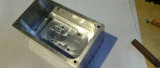
It is unlikely that you can make the core yourself, so it is better to use an unnecessary transformer of any type. You will need to carefully disassemble it and remove the “hardware” from there.
The next step is to make the frame. You can use various materials, for example, fiberglass. To calculate it, you can use the Power Trans program. It is worth noting that although this application can also calculate the number of turns, it is better not to use it for these purposes, due to not entirely correct results.
In the program, you can select the type of core, as well as set the cross-section of the core, windows and power of the product. Then click on calculation and get a finished drawing with dimensions. Next, all that remains is to transfer the drawing onto the textolite and cut out the required number of parts. After all the elements are prepared they are assembled into a frame.
Now you can proceed to preparing the insulating gaskets. They will be necessary to isolate the layers from each other. They are cut into strips of varnished fabric, fluoroplastic, mylar, or even thick paper, for example, which is used for baking. It is important to note that the width of the strip is made a couple of millimeters larger, and it is not recommended to mark the cutting lines with a graphite pencil (graphite conducts current).
At the last stage, the wire is prepared. Since it will be necessary to wind a 220 V 12 V 10a transformer, that is, a step-down transformer, the secondary coil will be made with a thick wire, and the primary coil with a thin wire.
Design calculation
Design calculations begin by finding the power that the secondary winding must withstand. Substituting into the formula: P = U * I, the values given to the conditions b for the secondary coil, you get: P 2 = 12 * 10 = 120 W. Assuming that the efficiency of the product will be about 80% (the average value for all transformers), we can determine the primary power: P = P 2/0.8 = 120/0.8 = 150 W.
Based on the fact that power is transmitted through the core, the value of P1 will depend on the cross-section of the magnetic circuit. The cross section of the core is found from the expression: S = (P 1)½ = 150 = 12.2 cm2. Now you can find the required number of turns in the primary winding to produce one volt: W = 50/ S = 4.1. That is, for a voltage of 220 volts you will need to wind 917 turns, and for a secondary voltage - 48 turns.
You might be interested in this: Checking the diode
The current flowing through the primary coil will be equal to: I = P / U = 150/220 = 0.68 A. Hence the diameter of the primary winding wire is calculated by the formula: d = 0.8 * (I)½ will be 0.66 mm, and for the secondary - 2.5 mm. The cross-sectional area can be taken from reference tables or calculated using the formula: S = 0.8 * d 2. It will be 0.3 mm2 and 5 mm2, respectively.
If suddenly a wire of such a cross-section is difficult to get, then you can use several conductors connected to each other in parallel. In this case, their total cross-sectional area should be slightly larger than the calculated one.
Winding technique
To wind the product, the made frame must be clamped on the axis and centered . It is better to first wrap the wire around some cylindrical object. For example, a spool of thread or a piece of pipe. A coil of wire is placed opposite the clamped frame. The wire is placed on the base and made several turns around it. Then they begin to rotate the frame body. In this case, you should carefully ensure that each turn lies next to the other and does not intersect it. After each layer, two turns of insulation are applied.
Once the primary winding is wound, the wire must be brought out to the side to form a lead. The rest of the wire is cut off. Before applying the secondary winding, several layers of insulation are laid and the whole process is repeated, but with a wire of a thicker cross-section. Upon completion of the work, the free ends of the coils are soldered to the terminals. Using a tester, the coils are checked for breaking.
There are some nuances when winding that it is advisable to know. During winding, the wire may accidentally break. In this case, you will need to strip the broken ends, twist them and solder them. Carefully insulate the soldering area, for example, by placing two layers of insulating paper. When winding, to increase the electrical strength of the product, it is recommended to impregnate each layer. This prevents vibration of the wire. Epoxy or acrylic based varnishes are used as impregnation.
Now all that remains is to connect the transformer from 220 to 12 to the power source. The connection to it occurs in a parallel circuit. Using a multimeter you can check the output voltage. To do this, it switches to the AC signal measurement mode.
If in the future it is necessary to obtain a constant signal, then a diode bridge (rectifier) with an electrolytic capacitor (smoothing filter) is connected to the secondary winding of the transformer. But it should be taken into account that for a current of 10 amperes you will need a corresponding rectifier unit capable of withstanding such a current with a margin of about 15%.
Thus, even a novice radio amateur can make a step-down transformer on his own. The main thing is to perform the correct calculation. And the manufactured product will certainly find its application.
How to check a step-down transformer 220 to 12V using a multimeter
If you have a step-down transformer and it is not known whether it is working or what its output voltage is, you can use a multimeter. However, it should be understood that incorrect testing can damage the measuring device. Let's look at the algorithm of actions:
- We visually find the primary and secondary and secondary windings. It's easy to do. The cores of the primary winding are always thinner.
- We set the multimeter switch to set the AC current to the minimum (usually 200 V).
- We apply voltage to the primary winding.
- We take readings from the secondary winding. If there are more than two contacts, we check them alternately. It is possible that, in addition to 12 V, the transformer is capable of delivering 24 and 36 V.
How to make a 220 to 12V transformer with your own hands
To make your own step-down transformer, you will need the following materials:
- a core that can be taken from an old TV;
- varnished fabrics;
- thick cardboard;
- boards and wooden blocks;
- steel rod;
- glue and saw.
First, let's look at the option of making a simple machine for winding wire.
| Illustration | Action to be performed |
| This is the simplest device for winding wire onto a reel. The diagram clearly shows how it can be assembled. However, there are more convenient devices that will speed up the process. | |
| Using an ordinary vice, a steel rod and a brace (hand drill), you can assemble a winding device that will save effort and time. | |
| Another device you can’t do without. Often old coils are used to make a transformer. It is this machine, together with one of the previous devices, that will allow you to carefully rewind the wire from one reel to another. |
Now we should consider making a cardboard frame onto which the wire will be wound directly.
| Illustration | Action to be performed |
| The dimensions of the frame are measured according to the core (it should fit inside quite tightly). Based on the fact that the core can be either made of ordinary plates or with a perforation, we invite the reader to familiarize themselves with both options. | |
| We make a pattern according to the dimensions, which is glued together. For fixation, you can use any glue, but it is better to give preference to waterproof one. The best option would be epoxy. | |
| And here you can see the size ratio of the prefabricated frame, which is more difficult to manufacture, but more reliable and does not require gluing. Remember that failure to comply with the parameters may lead to unstable operation of the transformer. |
When everything you need is ready, you can start winding. This work also has its own nuances that should be taken into account.
| Illustration | Action to be performed |
| The wire should be unwound from the “donor” coil from the top, and wound, on the contrary, from the bottom up. The distance between the coils should not be less than a meter. The wire is held with the right hand, and rotation is done with the left. | |
| Terminals for various voltage values are sealed using insulating gaskets. They can be made from wound wire or soldered a flexible lead to it, which is more convenient. The place of adhesion must be isolated. The lead is passed through a hole in the cheek and fixed. In order not to get confused later (if there are several conclusions), it is better to label it immediately. | |
| The fixing insulating pads are glued, however, even in this case, additional fixation is necessary. | |
| The figure shows how the fixing insulating pads are clamped with a wound wire. It is important to do everything according to the instructions - only in this case can you hope for a positive result. Remember that the turns of the wire must fit tightly to each other - this will ensure a stable magnetic field of the coil. |
Calculation of the number of turns of the primary and secondary windings
The main work in the manufacture of a transformer can be called calculating the number of turns of the primary and secondary windings. On average, for a converter of 90−150 W, the number of turns per 1 V equal to 50 Hz / 10 = 5 is taken into account. The total number is calculated using the formulas:
- W1 = 220 × 5 = 1100;
- W2 = 12 × 5 = 60.
We get the required number of turns of the primary winding - 1100, and the secondary - 60.
The essence of the device
A transformer is an electronic device used to convert an alternating signal of one amplitude to another without changing the frequency. It is difficult to find electrical equipment that does not contain such a product in its circuit. It is a key link in the transfer of energy from one part of the chain to another.
The appearance of the transformer became possible after the invention of the induction coil in 1852 by the German mechanic Ruhmkorff. His device was similar to a spool for winding threads, but instead of the latter, wire was used. Inside the coil there was another similar structure. When current was applied to the lower coil, the voltage was also recorded on the upper coil. This was explained by a phenomenon called inductance.
It is not known for certain who exactly invented the transformer. In 1831, Faraday, while conducting experiments, discovered that electricity arises in a closed circuit when the magnetic field changes. He also drew a rough diagram of what the transformer should look like. Using a steel core and two coils in 1876, the Russian scientist Yablochkov actually made the prototype of a modern device. When a current was applied to one of them, he observed the occurrence of magnetic induction, leading to the appearance of a current on the other. At the same time, the voltage on the coils was different due to the different number of turns.
The appearance of such a design prompted other scientists to conduct research, which resulted in the technology for manufacturing a modern transformer.
Operating principle
Modern industry produces transformers that differ in both appearance and characteristics. But they are all united by the principle of operation and five design elements. To understand how a step-down transformer works from 220 to 12 volts, you need to know these main parts of the product . These include:
- Core. In another way it is called a magnetic circuit. Its purpose is to conduct magnetic flux. Based on the type of execution, cores are divided into three groups: planar, strip, and molded. They are made from electrical steel, ferrite or permalloy, that is, materials that have the ability to be highly magnetized and have conductive properties.
- Windings They are a conductive wire wound in turns. The material used for its manufacture is copper or aluminum.
- Frame. It is used for winding windings on it and is made of insulating material.
- Insulation. Protects coils from interturn short circuits, as well as their direct contact with conductive parts of the structure. The most commonly used materials are varnish, clipper tape, and varnished cloth.
- Mounting terminals. To prevent breakage of the windings during installation, special terminals are made in the structure, allowing the power source and load to be connected to the transformer.
The main part of the winding is the turn. It is because of this that a magnetic force is created, which subsequently leads to the appearance of an electromotive force (EMF).
Thus, the transformer is a closed circuit (core) on which coils (windings) are located. Their number can be two or more pieces (with the exception of an autotransformer). The coil connected to the power source is called primary, and the one connected to the load is called secondary.
You might be interested in: Sequence in the discovery of electricity
When connected to a source of alternating energy, a time-varying current (sinusoidal) begins to flow through the primary winding of the device. It creates an alternating electromagnetic field. The magnetic induction lines begin to penetrate the core in which they are short-circuited. As a result, an emf is induced on the wound turns of the secondary coil, which creates a current when the terminals are connected to the load.
Characteristics and types of product
The potential difference arising between the terminals of the secondary winding depends on the transformation ratio, which is determined by the ratio of the number of turns of the secondary and primary coils. Mathematically, this can be described by the formula : U2/U1 = n2/n1 = I1/I2, where:
- U1, U2 - respectively, the potential difference on the primary and secondary windings.
- N1, N2 - number of turns of the primary and secondary coils.
- I1, I2 - current strength in the windings.
Based on the type of core, 12 V transformers are divided into ring, W-shaped and U-shaped. According to their design, they are: armored, rod and toroidal (ring). The rod type is assembled from U-shaped plates. The armored version uses side rods without windings. This type is the most common, since the windings are reliably protected from mechanical damage, although the cooling efficiency decreases.
The toroidal transformer has the best characteristics. Its design promotes good cooling. Effective distribution of the magnetic field increases the efficiency of the product. This type is the most popular among radio amateurs, as the simplicity of the design allows it to be quickly disassembled and assembled. For example, very often, it is on the basis of a torus that homemade powerful welding machines are made.
The main parameters of the product include:
- Power. Indicates the amount of energy transmitted through a device without causing damage to it. It is determined by the thickness of the wire used to wind the coils, as well as the dimensions of the magnetic circuit and the frequency of the signal.
- Efficiency It is determined by the ratio of the power spent on useful work to the power consumed.
- Transformation coefficient. Defines the conversion method.
- Number of windings.
- Short circuit current. Determines the maximum current that the device can withstand without burning out the windings.
You may be interested in Description of the megohmmeter, purpose of the device and principle of operation
Prices for transformers 220 to 12 volts
Let's consider at what price you can buy 220 to 12 volt transformers on the Russian market. Prices are as of April 2018.
| Photo | Brand | Power, W | Average cost (as of April 2022), rub. |
| Feron | 60 | 150 | |
| TRA54 | 200 | 500 | |
| TRA110 | 250 | 375 | |
| Pondtech | 75 | 4200 | |
| Relco | 250 | 4100 |
As you can see, the price range is quite wide. It depends on the brand and quality of components, which means you shouldn’t think that a step-down transformer for 150 rubles. will work for a long time.
Let's sum it up
Before purchasing a step-down transformer for your home, it is important to calculate all the parameters. You should not treat this carelessly, because the durability of the converter depends on the correctness of the calculations. If you decide to make such a device yourself, then you need to be even more careful about the calculations. Unless, of course, the home master expects to use a ready-made converter.
We hope that our dear reader has found the information he needs in today’s article. If you have any questions on the topic, ask them in the discussions below. The editors of Seti.guru will be happy to answer them. And perhaps someone has experience in making step-down transformers (whether successful or not). In this case, please share it with novice home craftsmen. And finally, we suggest you watch a short but very informative video on today’s topic.