Modern power supply systems are built on the basis of standard diagrams that take into account methods of grounding the equipment connected to them. This is done in order to protect the end consumer, as well as personnel working at electrical installations. When organizing modern networks, cables are traditionally used that include not only a phase core, but also a working neutral N, as well as a protective PE conductor. In some cases, these two types of buses are combined into one common PEN core. To understand their functional purpose, you will first have to find out what a PE bus is and how the color marking of the remaining conductors is carried out.
Types of grounding systems
Known electrical equipment protection systems differ in a number of ways, according to which they are divided into the following types: TN-S, TN-C, TN-CS, TT, and IT. The icons included in these designations are deciphered as follows:
- T stands for ground (from the French "Terre" or earth).
- N is the connection to the transformer neutral.
- I means isolated.
- C – combining the functions of the working and protective neutral conductors (“common”).
- S – separate use of these cores (“select”).
According to the PUE, TN-C means a system grounded to neutral with combined protective and working conductors.
The designation TN-CS means that in some part of the power circuit two conductors are laid together, and then they are separated according to functionality.
Classification of zero buses
According to the functions performed, the zero buses included in the power supply system are divided into the following types:
- N – functional or working “zero”, which is a conductor for load currents.
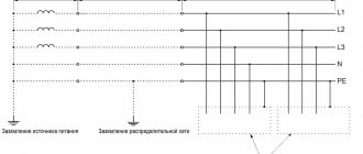
- PE is a specially laid protective “zero” that provides the ability to organize grounding at the receiving end in a convenient place.
- PEN is a conductor that combines the functions of both of these buses.
N
P.E.
PEN
Each of the conductors in the diagrams is highlighted in a certain color (N - blue, PE - yellow-green, and PEN - a combination of these). They must be selected according to their cross-section, which should not be less than the same indicator for phase buses.
This decoding also makes it possible to understand why it is necessary to separate the PEN conductor, what it serves, and how grounding can be arranged on the consumer side.
Why divide PEN into two parts?
Correct division
Dividing the PEN wire into PE and N cores only makes sense when each of them is intended to be used for its intended purpose. This can be done in the following cases:
- in a private (country) house, when a tap from the PE bus is made in the distribution board, used to organize local re-grounding;
- in a city apartment building, where the residents of the entrance agreed to install a common grounding loop on the street next to the entrance;
- a copper descent is carried out from the PE wire to a homemade ground loop.
To implement grounding with a homemade circuit, permission from the relevant energy services and approval from the housing and communal services will be required.
When in city houses a jumper is placed between the buses in the driveway panel, there is no need to talk about full grounding. The regulatory documentation on this matter provides a recommendation without a detailed explanation of the effect of such “grounding”.
Grounding and protective electrical safety measures
Where should the grounding conductor be connected if a CT is installed in the PEN conductor connecting the neutral of the transformer or generator to the PEN bus of the switchgear up to I kV? Answer. It should not be connected directly to the neutral of the transformer or generator, but to the PEN conductor, if possible directly to the CT. In this case, the division of the PEN conductor into RE and N conductors in the TN-S system must also be carried out behind the CT. The CT should be placed as close as possible to the neutral terminal of the transformer or generator.
What should be the resistance of the grounding device to which the neutrals of a generator or transformer, or the terminals of a single-phase current source are connected? Answer. There should be no more than 2, 4 and 8 Ohms at any time of the year, respectively, at 660, 380 and 220 V three-phase current source or 380, 220 and 127 V single-phase current source. This resistance must be ensured taking into account the use of natural grounding conductors, as well as re-grounding conductors of PEN or PE conductors of overhead lines up to 1 kV with a number of outgoing lines of at least two.
What should be the resistance of the ground electrode located in close proximity to the neutral of a generator or transformer, or the output of a single-phase current source? Answer. There should be no more than 15, 30 and 60 Ohms, respectively, at line voltages of 660, 380 and 220 V of a three-phase current source or 380, 220 and 127 V of a single-phase current source. If the earth resistivity is ρ > 100 Ohm×m, it is allowed to increase the specified standards by 0.01 ρ times, but not more than tenfold.
At what points in the network should the PEN conductor be re-grounded? Answer. Must be performed at the ends of overhead lines or branches from them with a length of more than 200 m, as well as at the inputs of overhead lines to electrical installations in which automatic power off is used as a protective measure in case of indirect contact.
What should be the total resistance to spreading of grounding conductors (including natural ones) of all repeated groundings of the PEN conductor of each overhead line at any time of the year? Answer. There should be no more than 5, 10 and 20 Ohms, respectively, at line voltages of 660, 380 and 220 V of a three-phase current source or 380, 220 and 127 V of a single-phase current source. In this case, the spreading resistance of the grounding conductor of each of the repeated groundings should be no more than 15, 30 and 60 Ohms, respectively, at the same voltages. If the earth resistivity is ρ > 100 Ohm×m, it is allowed to increase the specified standards by 0.01ρ times, but not more than tenfold.
Grounding devices in electrical installations with voltage up to 1 kV with an insulated neutral
What condition must be met by the resistance of the grounding device used for protective grounding of the EPC (exposed conductive part) in an IT system? Answer. Must meet the following conditions:
R ≤ U pr/I
where R is the resistance of the grounding device, Ohm;
U pr – touch voltage, the value of which is assumed to be 50 V; I is the total ground fault current, A.
What are the requirements for the resistance values of the grounding device? Answer. As a rule, it is not necessary to take this resistance value less than 4 ohms. A grounding device resistance of up to 10 ohms is allowed if the condition is met
R ≤ Upr/I,
and the power of generators or transformers does not exceed 100 kVA, including the total power of generators or transformers operating in parallel.
Grounding switches
What can be used as natural grounding agents?
Answer. Can be used:
- metal and reinforced concrete structures of buildings and structures in contact with the ground, including reinforced concrete foundations of buildings and structures with protective waterproofing coatings in non-aggressive, slightly aggressive and moderately aggressive environments;
- metal water pipes laid in the ground;
- casing pipes for drilling wells;
- metal sheet piles of hydraulic structures, water conduits, embedded parts of gates, etc.;
- rail tracks of main non-electrified railways and access roads in the presence of a deliberate arrangement of jumpers between the rails;
- other metal structures and structures located in the ground;
- metal shells of armored cables laid in the ground. Aluminum cable sheaths are not allowed to be used as grounding conductors.
Is it allowed to use pipelines of flammable liquids, flammable or explosive gases and mixtures, and sewerage and central heating pipelines as grounding conductors? Answer. Not allowed to use. The specified restrictions do not exclude the need to connect such pipelines to a grounding device for the purpose of equalizing potentials.
What cross-section should the grounding conductor connecting the working (functional) grounding electrode to the main grounding bus in electrical installations up to 1 kV have? Answer. Must have a cross-section of at least: copper - 10 mm>2, aluminum - 16 mm2, steel - 75 mm?.
What should be used as the main grounding bus inside the input device?
Answer. A PE bus should be used.
What are the requirements for the main grounding bus? Answer. Its cross-section must be no less than the cross-section of PE (PEN) - the conductor of the supply line. It should, as a rule, be copper. It can be used in steel. The use of aluminum tires is not permitted.
What are the requirements for installing the main grounding bus? Answer. In places accessible only to qualified personnel, for example, switchboard rooms of residential buildings, it should be installed openly. In places accessible to unauthorized persons, for example, entrances and basements of houses, it must have a protective shell - a cabinet or drawer with a door that can be locked with a key. There must be a sign on the door or wall above the tire.
How should the main grounding conductor be installed if the building has several separate inputs? Answer. Must be completed for each input device.
Conductor splitting options
Input distribution device
In the distribution board, where the PEN conductor is separated, grounding is organized using the splitting method, but a jumper must be installed between N and PE. It is important that the earth bus is connected first, and only after that the connection of the working core is completed. In this situation, there are four possible options for connecting the PE wire:
- There is no jumper between it and conductor N - the working zero contact and the grounding bus are not electrically connected. An RCD is also not installed in the protective circuit.
- There is a jumper between these terminals, but the RCD is not installed.
- PE for grounding and N are short-circuited and an RCD is installed.
- There is no jumper, but there is an RCD.
In the first case, the “physics” of the activation of protective circuits looks like this:
- The emergency phase hits the device body.
- Then it goes to the ground bus.
- Further along it goes to the circuit of the transformer substation.
When considering the problem, it is important to take into account the resistance of the grounding circuit, which usually does not exceed 20 Ohms, taking into account the cross-section of the PE conductor in mm. square. In the event of an accident, the short-circuit current will not be enough to turn off the input circuit breaker. The protective circuit will function until the damaged area on the receiving side burns out completely. This situation will not cause any significant harm to a person, but the equipment will suffer serious damage (the worst case scenario is that it catches fire and ignites).
There is a jumper, but there is no RCD
Separation diagram of a PEN conductor for a single-phase network.
In this case, the length of the supply line (removal of the location of its damage from the input distribution panel), which determines the resistance of the wire for charge flow, plays an important role. In the event of an emergency phase short circuit to the frame of damaged equipment, the leakage current first flows to the grounding bus. Then it has only two ways: part of the emergency electricity goes into the ground, and the other along the zero bus will trigger the machine at the input. In the situation considered, the jumper is used in case the AV does not work for some reason. But since the latter is practically impossible, it makes no difference whether it is present or absent.
There is a jumper and an RCD is installed
Since all protective and working conductors have a certain resistance, in this case the RCD should operate normally. When a short circuit occurs on the housing, the leakage current first flows to the RCD itself and only then goes to the input of the residential building. Here, as in the previous case, it is divided into two parts: some part of the whole goes into the ground, and part returns through the jumper to the panel, turning off the input machine. However, as a rule, things don’t come to this, since the RCD is triggered much faster.
In this situation, the jumper does not have much significance and is only a safety net, just in case: if suddenly, by a strange coincidence, the RCD does not work.
There is no jumper and an RCD is installed
This circuit will work in the same way as if there was a jumper. The only difference from the previous case is the lack of insurance if the RCD fails, which is unlikely. If this does happen, the circuit will begin to work according to the first of the considered options. In this case, the input device does not operate until the short circuit to the housing is transformed into a phase short circuit.
Typical phase splitting errors are associated with violations of the commutation order. You cannot connect the working conductor first and only after it connect the grounding. Another typical mistake is the reluctance to install an RCD. In circuits with artificial splitting of the PEN conductor, the presence of a residual current device is mandatory.
How to divide a PEN conductor into PE and N
Today I decided to tell you about where and how to correctly divide the PEN conductor into PE and N. I was prompted to this idea by endless debates and discussions on thematic forums.
In this article, referring to the clauses of the current regulatory documents (PUE, PTEEP, various GOSTs), I will try to give you the final correct and comprehensive answer to this question.
Why do you need to split the PEN conductor?
First, let's decide why we need to separate the PEN conductor. To do this, let's turn to the latest 7th edition of the PUE, clause 7.1.13, which says that:
This means that all electrical installations with a voltage of 380/220 (V) must have a TN-S grounding system, or, in extreme cases, TN-C-S. But what to do when in Russia we still have electrical wiring in old housing stock made according to outdated standards with a TN-C grounding system.
Thus, with any reconstruction (change) or modernization of the electrical installation, and also if you are not indifferent to the electrical safety of your family, it is necessary to switch from the TN-C grounding system to the more modern TN-S or TN-C-S, but at the same time it is necessary to perform separation PEN conductor to zero working N and zero protective PE, and correctly. This is where confusion and constant disagreement begin.
For information:
You can read the articles about how we carried out a major overhaul of the electrical wiring of a residential apartment building, and you will see with your own eyes the current state of the electrical wiring and other engineering networks and communications of most residential buildings.
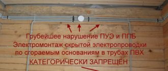
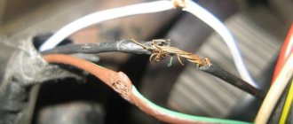
Let me give you an example of the driveway panel of one of the residential buildings where we carried out electrical wiring repairs - horror:
In this article I will not focus on grounding systems, because I wrote about each separately, indicating their advantages and disadvantages.
So, let's move on to the issue of dividing the PEN conductor into zero working N and zero protective PE.
How to divide a PEN conductor into PE and N?
To more clearly present what is written below, I will give examples from my practice with real photographs. As an example, consider the food supply of an apartment building, such as a Khrushchev building.
PUE, clause 1.7.135:
From the point where the PEN conductor is divided into zero working N and zero protective PE, their further connection (combination) is prohibited.
At the separation point, in our example it is ASU-0.4 (kV), two busbars (or clamps) are installed, which must be connected to each other and marked:
— PE bus or it is also called GZSh (I wrote about it in more detail in the article about the requirements for the GZSh bus);
- N bus.
Any wire or bar of the same cross-section and material can serve as a jumper. Some of my electrician colleagues install two jumpers at the edges of these busbars, which, in principle, does not contradict the requirements of the PUE.
I emphasize that busbars or clamps must have separate connection points for the corresponding PE and N conductors, and not be connected in one place under one bolt or clamp.
The N bus is installed on special insulators, and the PE (GZSh) bus is attached directly to the housing of the ASU-0.4 (kV).
We read the PUE, clause 1.7.61:
And now we need to re-ground the PE bus (GZSh), to which the PEN conductor of the input cable is connected. The above paragraph says that natural grounding can be used as re-grounding. I recommend that you install a grounding device, abbreviated as Z.U. You can read about how you can do this yourself in my article about installing a grounding device.
After installing the grounding device (GD), it is necessary to check its resistance. An electrical laboratory at your place of residence will help you with this.
If the resistance of the mounted grounding device meets the requirements of PTEEP and PUE, then we connect the PE (GZSh) bus to our grounding device using a grounding conductor. Well, that’s all, from this point of the electrical installation the input PEN conductor is divided into zero working N and zero protective PE conductors.
PEN conductor separation schemes
I will give an example of a three-phase input circuit with a meter for direct (direct) connection to the network:
The layout of the above diagram may vary slightly. For example, instead of an input circuit breaker, a three-pole switch can be installed, and after the meter, input fuses and an RCD can be installed. The same applies to group load circuit breakers - fuses can be installed instead.
Let's move on to an illustrative example: a residential 4-story apartment building is powered from a transformer substation (TS) located in the courtyard by an AVBbShv cable (4x70).
In this case, we connect the phase conductors (A, B, C) of the input cable to a switching device - a three-pole switch, and the combined PEN conductor of the input cable - to the PE bus (GZSh). Let's look at the diagram:
And here are photographs of this same ASU:
Here is another clear example - this is a diagram of a three-phase input with a meter connected via a current transformer:
The input cable brand AVBbShv 2 (3x70) is laid to the ASU with two threads.
The three cable cores are phase conductors (A, B, C) connected to an input three-pole switch. The metal sheath of the input cable is used as a PEN conductor, which is connected directly to the PE bus (GZSh).
After the input switch, input fuses PPN-35 with a rating of 250 (A) and current transformers with a transformation ratio of 200/5 are installed. To protect against short circuits and overloads of group loads, in our example this is the main electrical wiring (risers) of the entrances, PPN-33 fuses with a rating of 50 (A) are used.
Here is an example of a single-phase input circuit for a private house or cottage receiving power from a two-wire overhead SIP line with further separation of the PEN conductor in the input panel:
Here I would like to add that the input machine must be installed in a plastic box so that it can be sealed, otherwise problems may arise with the energy supply organization when putting the electrical installation and meter into operation. And please also note that the zero buses N1 and N2 are NOT connected to each other.
I am still more inclined towards this single-phase power supply scheme at home with PEN conductor separation in the input panel and I always recommend and advise it.
But many experts, including my colleagues in the shop, often refer to the still existing GOST R 51628-2000, which, by the way, was last edited in March 2004. And there it is recommended to use the following scheme for single-phase power supply of single-family and rural residential buildings:
My opinion on this matter is the following: both schemes are correct, but it is better to refer to newer issues of scientific and technical documentation (I mean PUE) and adhere to their norms and requirements, which I talked about at the beginning of this article.
I forgot to say: do not forget to protect your “home” from overvoltages arising from lightning discharges or switching of various electrical equipment, using an SPD or surge arrester. In future articles I will talk about this in more detail.
After the considered scheme options, I would like to remind you of the PUE, clause 1.7.145:
After you have upgraded your input panel, installed PE (GZSh) and N buses there, and installed the G.U. (ground loop), then you should pay attention to the following clause 7.1.87 and clause 7.1.88 7 th edition of the PUE, which states the following:
As can be seen from paragraph 7.1.87, the potential equalization system must be performed at the entrance to the building, i.e. this is another argument in favor of dividing PEN into zero working N and zero protective PE at the entrance to the building, i.e. at the ASU. Read about this below.
I hope that I have fully covered the topic of dividing the PEN conductor, but at the end of the article I decided to answer the most common questions that may still arise during the reading process.
Place where the PEN conductor is divided into PE and N
The most common (probably) question that constantly forces active communication on thematic forums is where the PEN of the conductor is divided. There are two possible answers - one is correct, and the other is not quite correct.
Let's start with the right one:
1. Input switchgear (IDU)
The most correct place for dividing the PEN conductor into PE and N is the input switchgear VRU-0.4 (kV) or VRU-0.23 (kV) of a separate building. A separate building in our understanding is a residential apartment building, a cottage, a garden or country wooden house, etc.
There is one condition that I cannot help but mention: power supply to a separate standing building must be carried out by a cable whose cross-section must be no less than 10 square meters. mm for copper or 16 sq. mm for aluminum. This is clearly stated in the PUE, paragraph 1.7.131:
How to understand this: if your cottage, house or other separate building is powered by a cable whose cross-section is smaller than that specified in clause 1.7.131, then its power supply should be carried out using the TN-CS system, i.e. with separate PE and N. There are cases when a separate building (for example, a bathhouse) is powered by a TN-C system with a cable with a smaller cross-section than allowed by clause 1.7.131 - in this case, the PEN conductor must be divided in another place - closer to the power source, for example, in distribution board, from where this building (bathhouse) is powered.
Here is another compelling argument in favor of the rules and requirements of the PUE for separating PEN conductors - this is GOST R 50571.1-2009. Clause 312.2.1 clearly states where and how exactly the PEN conductor should be separated. I quote:
The input of the electrical installation for a residential apartment building or private house is the input switchgear (ISU).
But now it’s not a very correct option.
2. Floor shield
Very often, visitors to my website, as well as various forums, are persistently interested in the question of separating the PEN conductor in the floor (access) panel.
I answer: see point 1.
If you are not convinced, then know that separating the PEN conductor on the floor panel is a gross violation of the existing electrical wiring design of a residential building. Therefore, you have no right to interfere with the existing circuit with your installation. God forbid, if something happens after the intervention, then first of all you will bear full responsibility for it: a fine, administrative or criminal liability.
Therefore, I strongly recommend dividing the PEN conductor into PE and N only at the entrance to the building, period.
Okay, we’ve decided on this, but what to do and how to switch from the TN-C system to the TN-CS system?
Solutions for moving from a TN-C system to a TN-CS system
What advice can I give you here?
1.
Wait for the opportunity to include your residential apartment building on the list for major repairs, according to the current federal program. In this case, everything will cost you free. The question remains whether your home will be included in this program at all. You can find out this at the office of your management company.
2.
Pay for the services of specialists who will draw up a project, approve it in all instances and carry out a major overhaul of the electrical wiring of the entire residential building, or, in extreme cases, transfer your house to the TN-CS system, install a new ASU, lay new wires for mains (risers) and start your apartment will have a full-fledged “three-wire”: phase, neutral and ground.
This financial option will be quite expensive, so we read the third option, which also has the right to life.
3.
Contact all residents of the house (at least the majority) to the management company (MC) with an offer of fruitful and close cooperation. For example, you can install a grounding device (grounding loop), I talked about this in detail, or help in laying electrical wiring mains (risers) across the floors. So to speak, act “together”... Well, the project for all changes, naturally, will fall on the shoulders of the management company.
Perhaps this option is more suitable for HOA members, but nevertheless you can try. As a result, through joint efforts, your house will probably be transferred to the TN-CS system, a five-wire main (riser) will be laid along the floors or shafts, and you will only have to, if the opportunity arises, introduce a three-wire input into your apartment.
What to do when the wiring in the apartment is made according to modern PUE requirements, but the supply line is still two-wire?
I answer: in this case everything is very simple. In the apartment panel, you connect all the PE protective conductors to your PE bus, but you do not connect the PE bus itself anywhere and leave it “in the air” until your house is transferred to the TN-CS system.
Features of PEN conductor separation
In private houses and city apartments, in order to prevent the theft of electricity, representatives of the controlling organization have the right to demand that the PEN wire be extended to the meter. And only after the metering device do they allow it to be divided into a protective bus PE and a working bus N. Such a connection does not contradict the requirements of the PUE, but the division made before the meter looks much more natural.
Scheme for single-phase power supply of single-family and rural residential buildings
If you first make a separation and then seal the input machine, there can be no objections from representatives of Energosbyt and inspectors.
Features of performing separation
The separation of the combined protective conductor PEN into zero N and protective PE is carried out at the input of the electrical installation. In this case, the PE protective conductor is sometimes called the main ground bus.
In relation to individual residential buildings, the input panel is naturally chosen as the separation point; for households in apartment buildings, it is advisable to carry out this procedure at the ASU.
The separation can be performed in both single-phase and three-phase networks. There is no fundamental difference between them except for the number of phase wires.
To avoid unnecessary losses of electricity, it is advisable to perform the separation before the meter.