Connection diagrams
So, the operating principle of the circuit breaker is now clear, you can proceed directly to its connection diagrams. Let's start with the fact that machines can be connected to single-phase and three-phase networks. What machines are needed for this? If the conversation is carried out from single-phase networks with a voltage of 220 volts, then either a single-pole device or a two-pole device is usually installed in them. The circuit itself will depend on whether it uses a ground loop or not.
If two wires enter the house (zero and phase), then a single-pole version can be installed in the distribution cabinet. In this case, the phase circuit will pass through the machine itself. If three wires enter the house (phase, neutral and ground), then the common circuit breaker must be two-pole. That is, a phase is connected to the first terminal of the device, and zero to the second. Grounding is routed to consumers (lights and sockets) through a separate terminal box. Next, the wires from the circuit breaker are routed to the meter, then to single-pole circuit breakers installed in groups, but as described in the first case. By the way, below is the system for connecting the machine.
As for the three-phase network, in this case it is best to install three-pole or four-pole structures. Everything here is exactly the same as in the case of a single-phase connection. That is, if the house uses wiring without grounding, then three phases of the power supply are connected to the fixed contacts. The neutral wire is routed as a separate circuit to consumers (sockets and lamps). If the house has a grounding system, then a four-pole model is installed, that is, three phases and zero will be connected to the device, and the grounding loop will go as a separate line to consumers.
Sometimes connecting a circuit breaker is associated with the correct implementation of some nuances of the entire process. Namely, by connecting wires to the device
What do you need to pay attention to?
Each model has its own requirements regarding the cross-section of the inserted wire and the length of the insulating sheath
This must be indicated in the product passport. Most often, the wire needs to be stripped to a length of 0.8 to 1.0 cm. It is important to understand that placing a wire with insulation in a clamp is unacceptable, because the diameter of the insulation is larger than the diameter of the core itself, so the contact between the clamp and the core will either be weak or completely absent. The wire is fixed in the machine with a screw, which is tightened with a screwdriver. After fixing, you need to check the quality of the clamp; to do this, the wire itself must be tugged slightly. If a stranded conductor is used to connect the machine, then it is best to put a tip on its end.
How to choose the right RCD according to parameters
The choice of RCD must be carried out, paying attention to its rated and differential operating current.
Rated is the current for which the power contacts are designed. If it increases, they may fail. Differential is the operating current of the residual current device, that is, leakage.
Before choosing an RCD, it is useful to find out its price, quality and performance and compare these three parameters. Since choosing an RCD based on power and quality can be difficult for a non-professional, experts advise making a table of the parameters of the devices you like and using it to select a device with the best characteristics.
Rated current
When selecting by rated current, you need to know that the device is always placed in series with a circuit breaker to protect power contacts from overload and short circuit. If one or the other occurs, the device does not work, since it is not intended for this. Therefore, it must be protected automatically.
The next thing you should pay attention to: the rated current must at least match that declared for the machine, and it is better to be 1 step higher.
Differential current
- For electrical safety purposes, a differential operating current of either 10 mA or 30 mA is always selected. For example, you can install a 10 mA RCD on one electrical receiver. At the entrance to the house, a device with this value may operate too often, since the electrical wiring in the apartment has its own leakage limits.
- All other RCDs with a differential current above 30 mA are used for fire protection purposes. But when installing a 100 mA RCD at the input, a 30 mA RCD must be installed in series with it for electrical safety purposes. In this case, it would be advisable to install a selective RCD at the input so that it operates with a short time delay and allows a device with a lower rated current to operate.
Product type
According to the form of current leakage, all these devices are classified into 3 types:
- “AC” type device. This device is common due to its more affordable price. Triggers only when a sinusoidal current leak occurs.
- Device type “A”. Designed to operate upon the instantaneous or gradual appearance of excess current, which has a variable sinusoidal and pulsating constant shape. This is the most popular type, but has an increased cost due to the ability to control both constant and variable flow.
- Type “B” device. Most often used to protect industrial premises. In addition to responding to sinusoidal and pulsating shapes, it also responds to the rectified shape of a constant leak.
How to choose based on device characteristics and functions
The main parameter by which a circuit breaker is selected is the total current load from all connected electrical appliances
You also need to pay attention to other factors - network voltage, number of poles, housing security, wire cross-section, condition of electrical wiring
Determining the polarity of the machine
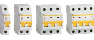
Depending on the type of electrical wiring, the pole of the machine is selected. For single-phase networks, single- and two-terminal devices are used; for three-phase electrical networks, devices with three and four poles are used.
Current selection
Current is the most important characteristic influencing the choice of machine. It is this indicator that determines whether the protection will work in an emergency. For electrical panels located near electrical substations, a 6 kA protective device should be purchased. In residential premises this value increases to 10 kA.
Operating or rated current
Operating currents are determined by the total load of all household appliances that the machine protects. The cross-section of electrical wires and their material should also be taken into account.
For the lighting group, 10 Amp circuit breakers are usually used. Sockets can be connected to 16 Amps. Heavy-duty appliances like electric stoves and water heaters require 32 amps at the circuit breaker.
The exact value is calculated as the total power of all household appliances divided by 220 V.
It is undesirable to greatly increase the operating current - the machine may not work in an accident.
Short circuit current
To select a circuit breaker based on short circuit current, you should use the rules of the PUE. It is prohibited to use switches with a breaking capacity lower than 6 kA. In homes, 6 and 10 kA devices are most often used.
Selectivity
This term refers to the disconnection in an emergency of only the problematic section of the electrical network, and not all the energy in the house. You should select machines for each group of devices separately. The input circuit breaker is selected for 40 A, then devices with a lower current are installed for each type of household device.
Number of poles
There are several types of machines: single-pole, two-pole, three-pole and four-pole. Single-terminal circuits are used in a single-phase network (one phase, two, three wires). The neutral is not protected in this case. Used for socket group or for lighting. A double pole switch is used for electrical wiring with one phase and two wires. Can be used as an input fuse for the entire network and to protect individual electrical appliances. Devices with two poles are the most common.
Replacing one two-terminal device with two single-terminal devices is prohibited by the rules of the Electrical Installation Code.
Three-terminal and four-terminal networks are used in a three-phase 380 Volt network. They are spilled by the presence of a neutral wire in a device with four poles.
Cable cross-section
The cross-section and material of the cables has a huge influence on the choice. Homes built before 2003 used aluminum wiring. It is weaker and needs replacement. It is impossible to install a new switch selected only by total power.
Copper cables carry higher currents than aluminum cables
Here it is important to take into account the cross-section - copper products with an area of 2.5 sq. mm. operate safely with currents up to 30 A
To determine the required value, use tables for calculating cable cross-section.
Manufacturer
You definitely need to pay attention to the manufacturer of the machine. It is better to purchase the device from a well-known, trusted company in a specialized store.
This will reduce the risk of buying a fake, and the purchased product will meet the stated criteria. Also, branded stores provide a guarantee on the switch.
Housing protection degree
Each switch has its own degree of housing protection. It is written as IP and 2 digits. Sometimes 2 Latin letters may be additionally used to describe auxiliary characteristics. The first number indicates the degree of protection from dust, the second – from moisture. The higher the number, the higher the security of the machine body.
Marking
The switch is marked with letters and numbers. It is deciphered as follows:
- letter A, B, C, etc. – class of the machine, means the instantaneous current limit;
- the number indicates the rated current at which the device operates in normal mode;
- A number in thousands of amperes is also indicated next to it, indicating the maximum current value at which the switch will respond.
The markings are indicated on the device body and in the relevant documentation.
Capabilities and purpose of multi-pole circuit breakers
The AB installation with two poles is designed to provide control:
- independent lines - in case of problems they are switched off simultaneously;
- indicators of each line - if there are faults, both are switched off;
- networks with direct current - the reasons for shutdown are similar.
The input device will turn off the voltage in the entire apartment or house if failures occur in at least one area. The bagger is convenient because de-energizing can be done manually.
Purpose of devices
A two-pole circuit breaker allows you to de-energize an apartment manually.
For a single-circuit circuit with single-phase wiring (grounded zero, neutrals short-circuited on the neutral buses), a two-pole circuit is not suitable. In this case, a single-pole switch is mounted.
If it is impossible to connect several devices to a common network, use a two-terminal network. The machine is installed because there is no neutral and phase at the transformer output. The electric current, cut off on one wire, may remain on the other. A two-pole device replaces differential protection systems and RCDs, which eliminates the cost of purchasing discrete devices.
Four- and three-phase models function in a similar way.
PUE allows the installation of a 2-pole circuit breaker at the input, but a grounding cable cannot be connected to it.
Installation
How to properly install circuit breakers in an electrical panel? First, DIN rails are screwed into it with self-tapping screws - these are metal plates, onto which all automatic devices and RCDs are then attached. The length of the DIN rail can be adjusted using a hacksaw. In addition, distribution terminal strips are attached to the shield. They can be for neutral wires and separately for ground wires. The modern configuration of the tires allows them to be mounted directly on a DIN rail.
Installing a two-pole circuit breaker on a DIN rail is very simple. Using a flat-head screwdriver, you need to pull out the snap-on bracket on the top of the case, attach the machine to the DIN rail and release the fastener. Removal is also carried out. According to the rules, the introductory machine is installed in the upper left corner.
Next you need to connect the wires. The scheme must be strictly adhered to. The phase and neutral input wires are connected to the two-pole circuit breaker from above, and the wires from below are discharged into the circuit
It is important not to confuse: the entrance is from above, the exit is from below, otherwise the machine may fail and will not perform its functions
You can connect machines using jumpers made of copper wire of the same cross-section as the circuit wire. Jumpers are required to connect two-pole circuit breakers in a row. And also with the help of combs - these are insulated buses, used to connect single-pole circuit breakers.
The ends of the wires are stripped using a special stripper tool or a sharp knife. Then they crimp the cable lugs with a hand tool using a crimper. If there is no such equipment, then you can simply tin the ends with a soldering iron using rosin and tin. When connecting wires to machines, it is necessary to tighten the bolts firmly with a screwdriver so that weak contact does not cause heating and damage to conductive materials.
The grounding wire always passes past the machines directly to the grounding bus. The neutral wires are connected to the neutral bus.
What parameters are used to select an input device?
The selection of an introductory machine is made taking into account a number of characteristics. You need to know them in order to choose the right VA for a specific electrical network:
Maximum short circuit current. If you are selecting a device for a summer house or rural home, in most cases a breaking capacity of 4.5 MA will be sufficient. For an ordinary city apartment, a 6 MA device is suitable. If there is a substation near your machine, you should install the machine at 10 MA.
- Operating current. We described above how to calculate it. Taking into account the obtained value, the rated current VA is selected.
- Time-current characteristic. The most common devices are class B, C and D. Type B machines are installed if high power devices are not included in the circuit. If medium-power devices (for example, a welding machine) are periodically connected to the network, a class C device is installed at the input. If high-power equipment is used, the input device must be type D.
Errors when choosing an RCD
From the point of view of insulation, there are no absolutely ideal devices; every electrical device has a natural leakage, albeit a very small one.
When choosing an RCD, you need to understand that the sum of natural leakage currents can cause false operation of the device. Based on this, there is a rule that states that the sum of the natural leakage currents of devices that are connected to a given residual current device should be no more than 1/3 of the rated leakage current.
For example, if a residual current device has a rated leakage current of 10 mA, then the sum of natural leakage currents should not exceed 3.3 mA, for 30 mA it is 10 mA, etc.
Therefore, in order to ensure that the selected RCD does not trigger falsely, you need to take into account the natural leaks of electrical appliances that are connected to it (quality manufacturers indicate the leakage current in the passport or on the device body).
ABB automatic machines. Their application, description, groves. Assembly and design
When purchasing an AV, you need to choose a rating so that it operates until the moment when the current does not exceed the capabilities of the wiring.
Expert opinion
Strebizh Viktor Fedorovich, leading construction foreman
So that you do not have to take out a calculator and independently calculate the cross-section of electrical wiring using formulas, we present a standard table in which it is easy to find the desired value. If you need an explanation of unclear points, write to me!
How to connect a two-pole machine
Connecting a two-pole circuit breaker yourself should not cause any particular difficulties, but entrust the matter to an electrician and do not risk working with potentially dangerous devices yourself. Of course, it’s easy to figure out how to connect everything with your own hands, but it is extremely undesirable to install such a mechanism alone - usually even electricians work on the connection in pairs. Therefore, it makes sense to ask someone to help and make sure nothing happens.
The installation of any mechanism of this type is carried out with permission. The procedure for obtaining it is simple; you only need to contact the housing and communal services or management company. If you don't do this, you risk getting a fine.
Attaching the device to a special metal rail is not difficult; just use a regular flat-head screwdriver to pull out the latch located on the back of the object’s body, place it on the special fasteners located on the rail, and release the fastener. The mechanism will latch itself, ensuring reliable fastening to the desired location. The wires are connected to the terminals with special clamping bolts. As a rule, the input wires of zero and phase are connected at the top, and the cores that need to be routed into the circuit are connected at the bottom.
Connecting the packet switch to the network
For a clear example, consider the diagram for connecting a batch switch to a single-phase meter:
The wires are stripped and secured in the screw terminals of the packet. For ease of connection, they are specially shifted relative to each other. For some types of PV, the ends of the wires need to be twisted into rings.
Note! The packager is connected exclusively to a phase break!
If there is a grounding contact on the device body, the grounding connection is made with a separate cable that is not a working zero.
If this is a three-phase network, then the packetizer will have 2 positions: all phases are closed or open. The wires are connected to the terminals on one side of the device, observing the phase order. The load wires are connected on the other side of the device in the same order, maintaining the diagonal opposite.
It is appropriate to use a batch switch where frequent power switching is necessary. But their frequency should not be more than 300 times in 1 hour. Thus, at rated voltage and current, as well as a power factor of 8.0, such switches can withstand up to 20 thousand switching operations.
Each bag has its own marking. It consists of several symbols. For example, like this: P BX – XXX XX XX XXX X. This table will help you decipher it:
Packet labeling table
Advantages of application over single-pole circuit breakers
Let's consider a situation where someone confused the phase with zero. Then, when the single-pole circuit breaker is turned off, the zero line is disconnected, and the phase remains in the circuit. A person, thinking that he has protected himself by turning off the machine, starts working and receives an electric shock. To prevent this from happening, after disconnecting the single-pole circuit breaker, you need to check the absence of voltage in the circuit with an indicator. But it is still safer to use a two-pole circuit breaker, which will completely de-energize the circuit.
In the case when the RCD has tripped, it is necessary to find a fault in the circuit. First of all, turn off all electrical appliances from the sockets. If this does not produce results, the branches of the circuit are switched off sequentially, but both zero and phase must be disconnected. A single-pole circuit breaker does not provide this opportunity. You will have to remove the zero on the bus, which is problematic, since it requires dialing to find the right wire. A two-pole machine copes with this task perfectly.
Thus, the advantages:
- Safety - the electrical circuit is completely broken.
- Ease of troubleshooting.
Features of the operation of single-pole and double-pole AV
A two-pole circuit breaker is always preferable to two single-pole ones.
The difference between a single-pole device and a two-pole circuit breaker is the number of networks controlled. Single-pole models are designed to turn off the current on one line. Two-terminal devices are responsible for two lines, comparing the electron flow indicators and establishing the correspondence of the values for the normal functioning of the network.
The devices will also differ in the design of the release. On bipolar ones, a tripping element is installed, which immediately turns off zero and phase in both automatic and manual modes. Another difference is the ability to be used in conjunction with complex equipment. A single-pole network can be connected to a single-circuit electrical network, a double-pole network can be connected if you have household appliances that are not allowed to be connected on the same line.
PUE rules prohibit the operation of single-pole models at the input.
How to properly connect machines after the meter
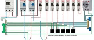
The installation of machines after the meter must be carried out according to the circuit diagram. The circuit should provide for the division of electrical wiring into several independent lines, each of which is protected by a separate circuit breaker and, if necessary, an RCD.
Note! If the dimensions of the distribution panel are limited, then it is possible to install differential circuit breakers that combine the functions of current protection and residual current devices. The cost of difavtomats is higher than the listed devices, but at the same time the wiring in the panel is simplified
The machines that will be installed after the meter must have a lower rating than the input one. If you install stronger ones, a fault in the network will cause the input circuit breaker to trip.
It is enough to protect lighting lines by installing a single-phase circuit breaker, and for sockets, two-pole protective devices are advisable, since a single-pole breaks only one wire.
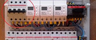
Connection diagram of machines in the electrical panel
Before you begin installing the machines, you need to carefully study their schematic design, because the installation diagram consists of several elements with different symbols.
Wiring diagram
Table 1. Elements used when installing an electrical panel.
| Name | Characteristic |
| Introductory machine | It is installed to protect the entire electrical wiring circuit. So, the cores of the main cable are fixed to the terminals of the machine. For ease of use, a switch is attached in front of the machine. It allows you to disconnect the current from the entire structure in order to carry out repair work. In this case, the power cable must also be connected to this switch. |
| Counter | It is placed after the machine guns. The main purpose of the meter is to control the consumed electricity . Sometimes it is fixed in another place even before the electrical panel along with the machines (on the landing). |
| Residual current device | The main function of the RCD is protection against electric shocks and fires . For example, in a small apartment, only one RCD is installed after the meter, because it is no longer required due to the minimum load. Sometimes several such devices are installed on lines where there is a large consumption of electricity. |
| Linear automata | They are required for lines to individual rooms. In the presence of high voltage or short circuit, they break the circuit, thereby preventing fire or short circuit . They are needed to protect various electrical appliances. |
| Differential machines | They are installed instead of several main circuit breakers with a protective device on separate lines for various household appliances. |
| Mounting rail | The rail is fixed to the rear wall of the base of the shield. Depending on the size of the box, the number of slats and modules may vary. In order to purchase a shield for a certain number of modules, a detailed drawing of the connections is first drawn up. |
| Comb | They are intended for the purpose of disconnecting the shield in order to connect the neutrals to the grounding connections. One shield has zero combs and grounding combs. |
| Distribution bus | They connect linear, differential circuit breakers and protective devices. They are reliably insulated, thanks to which they securely fix the machines through the input clamp. They are used for both phase and zero. |
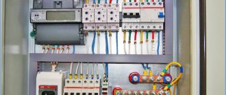
Electricity meter
Let's move on to connecting the circuit breaker
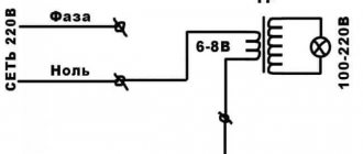
If there is voltage on your supply wire, it must be turned off before starting work. Then make sure there is no voltage on the connected wire using a voltage indicator. For connection we use VVGngP 3*2.5 three-core wire, with a cross-section of 2.5 mm.
We prepare suitable wires for connection. Our wire has double insulation, common outer and multi-colored inner. Let's decide on the connection colors:
- blue wire - always zero
- yellow with green stripe - earth
- the remaining color, in our case black, will be the phase
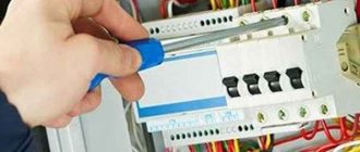
Phase and neutral are connected to the terminals of the machine, ground separately to the feed-through terminal. We remove the first layer of insulation, measure the required length, and bite off the excess. Remove the second layer of insulation from the phase and neutral wires, about 1 centimeter.
Unscrew the contact screws and insert the wires into the contacts of the machine. We connect the phase wire on the left, and the neutral wire on the right. Outgoing wires should be connected in the same way. After connecting, be sure to check again. Care must be taken to ensure that the wire insulation does not accidentally get into the clamping contact, as this will cause the copper core to have poor pressure to the machine contact, which will cause the wire to heat up, the contact to burn, and the result will be failure of the machine.
We inserted the wires, tightened the screws with a screwdriver, now you need to make sure that the wires are securely fixed in the contact clamp. We check each wire separately, swing it a little to the left, to the right, pull it up from the contact, if the wire remains motionless, the contact is good.
In our case, a three-wire wire is used; in addition to phase and zero, there is a grounding wire. In no case is it connected through a circuit breaker; a feed-through contact is provided for it. Inside, it is connected by a metal bus so that the wire passes without breaking to its final destination, usually sockets.
If you don’t have a feed-through contact at hand, you can simply twist the incoming and outgoing wires together using a regular twist, but in this case you need to pull it well with pliers. An example is shown in the picture.
The feed-through contact is installed as easily as a machine; it snaps onto the rail with a slight movement of the hand. We measure out the required amount of grounding wire, bite off the excess, remove the insulation (1 centimeter) and connect the wire to the contact.
Do not forget to make sure that the wire is well fixed in the contact clamp.
Suitable wires are connected.
If the circuit breaker trips, the voltage remains only on the upper contacts; this is completely safe and is provided for in the circuit breaker connection diagram. The lower contacts in this case will be completely disconnected from the electric current.
We connect the outgoing wires. By the way, these wires can go anywhere to a light, an outlet, or directly to equipment, for example, to an electric water heater or electric stove.
We remove the outer insulation and measure the amount of wire required for connection.
We remove the insulation from the copper conductors and connect the wires to the machine.
Prepare the ground wire. We measure out the required amount, clean it, connect it. We check the reliability of fixation in contact.
The connection of the circuit breaker has come to its logical conclusion, all wires are connected, and voltage can be applied. At the moment, the machine is in the down position (off), we can safely apply voltage to it and turn it on, to do this we move the lever to the up position (on).
By connecting the circuit breaker with our own hands, we saved:
- calling an electrician - 200 rubles
- installation and connection of a two-pole circuit breaker - 300 rubles
- DIN rail installation - 100 rubles
- installation and connection of a feed-through grounding contact 150 rubles
TOTAL: 750 rubles
*The cost of electrical installation services is shown in the pricing table
The structure and operating principle of a three-pole circuit breaker
A 3-pole circuit breaker consists of 3 single-pole devices housed in one housing and sharing a common switch lever. There are electromagnetic and thermal releases inside the protection device.
Internal organization
The electromagnetic release responds instantly to short circuit currents. According to the principle of operation, it resembles an ordinary electromagnet. If a short-circuit current flows through the machine, the electromagnetic release attracts the armature and sets the mechanics of the machine in motion. It opens the contacts of power circuits.
Circuit breaker design
The thermal release is similar to a bimetallic plate that is deformed by heat. It is characterized by slow response. To turn off the machine using the thermal release, it takes time for it to warm up to the desired temperature. Heat for heating is taken from the overload current flowing through the machine. Something similar is found in iron thermostats and kettle buttons.
Inside the differential automatic machines there is an additional unit - a current sensor. It is designed to compare currents flowing through phases. This design element allows the differential circuit breaker to turn off when voltage is lost in one of the phases. This function is especially important for the protection of electric motors.
Important! If your machine triggers without obvious overload, then you should pay attention to the reliability of its connection. Often, poor loose contact leads to heating of the machine. And heating leads to involuntary activation of the thermal release
And heating leads to involuntary activation of the thermal release.
Powerful three-pole circuit breakers have arc chutes. They are designed to interrupt the arc that forms between the contacts as quickly as possible at the moment the circuit opens. The use of arc chutes significantly extends the service life of the device. Thanks to them, contacts burn out much more slowly.
External elements
From the outside, the device has a standard design for protective devices. On top there are 3 screw terminals for connecting incoming wires. Below are similar screw contacts, but for the outgoing line. Between them there is an on and off lever. Many three-pole circuit breakers are equipped with a status indicator. Red flag or symbol “1” - the machine is turned on. Green or “0”—off. The main electrical parameters are indicated on the device body: rated current and time characteristic.
Additional Information. The design of some models of machines involves the use of a handle reminiscent of the one installed on the door. This handle is purchased at the buyer's request. Turning it turns the safety device on or off.
How many kilowatts can a machine withstand 16, 25, 32 and 40 Amps?
So, you have chosen, for example, a cable, and you need to select a machine for it, or vice versa, it is not so important.
The main thing is to know how many kilowatts this cable and machine can withstand. So let's get straight to the point. You need to select a circuit breaker as close as possible to the load that the electrical appliance consumes. For example, we have an electric boiler with a capacity of 6 kW. That is, the machine must withstand a 6 kW load, but also not be too powerful so that if something happens it can automatically turn off.
The easiest way is to calculate the power of the machine from the following table:
- A 10A circuit breaker will withstand about 2.2 kW;
- A 16A automatic machine can already withstand 3.5 kW;
- A 25A circuit breaker must withstand a 5.5 kW load;
- A 32A machine can withstand a load of 7 kW.
Accordingly, if you use this table for calculating circuit breakers, it becomes clear that to connect an electric boiler with a power of 6 kW, you need the closest circuit breaker in terms of value, namely 32 Amperes.
You can, of course, install a 25 Ampere circuit breaker, but it can also be an overload switch if the boiler operates at its full power.
Expert opinion
Strebizh Viktor Fedorovich, leading construction foreman
This value of short circuit current is determined in thousands of amperesat which the machine will remain operational after the circuit opens due to a short circuit. If you need an explanation of unclear points, write to me!
Difference between double-pole and single-pole circuit breaker
The difference between a single-pole and a double-pole switch is that the first monitors the technical parameters of several lines. Accordingly, the difference between two and three-pole is that in the first two lines are monitored, and in the second - three lines. When the voltage in one is exceeded, the device protects each line. The second device protects only one power line. At the same time, it is impossible to replace a two-pole circuit breaker with several single-pole ones due to the shutdown lever. The interlock is designed so that if there is a problem, both lines will be disconnected. In addition, the current will not evaporate. It will penetrate into a properly working device and a fire may occur.
Difference between double-pole and single-pole circuit breaker
Advantages and disadvantages
The advantages include reliable protection, the ability to control power, and ease of installation and maintenance. The main advantage is the de-energization of several conductors, regardless of the occurrence of an accident in any of them. Thanks to this, tension is completely removed.
You might be interested in: Installation of an electric meter
The disadvantages of a multi-pole protective device are the possibility of cable breakdown by electric current during a simultaneous short circuit of several electrical networks.
Note! They also include turning off the power to the electrical wiring during a breakdown of the thermal release, the inability to turn on the power after an emergency line breakdown and sensitivity to mechanical damage
Specifications
Technical characteristics of two-pole circuit breakers vary depending on price and manufacturer. The rated voltage is 240 watts, the rated current is from 6 to 63 amperes, the number of poles is from 1 to 4, the time-current characteristic is designated B, C and D.
Technical characteristics of electrical equipment
Installation and connection diagrams
A two-pole circuit breaker is installed according to the electrification plan. The housing is checked for damage and deformation before installation. The operation of the shutdown handle must be of high quality. During installation, the connection of a copper conductor using a lug and the connection of an aluminum cable using an end piece are taken into account. The upper group of stationary circuit breakers, conductor sealing with insulating tubes and protective tape, the distance of nodes and the location of the additional box are also taken into account.
The machine is placed on part of the DIN rail. The latch bracket is removed using a flat-head screwdriver and placed on the rail with fasteners. During installation, the usual scheme is used. An input switch is placed before the meter, after it a two-pole type device is mounted, and a neutral with a phase is connected on top. The cores are routed from below to the circuit. Wired copper jumpers are used to connect multiple devices together. The end is cleaned using a sharp object and crimped using a crimper.
Note! During installation of the device, work must be carried out by two specialists wearing protective rubber gloves after obtaining permission from the housing and communal services. The connection must be made to the panel without damage at the mounting location
ABB 2P (1P+N) or 1P machines? Double-pole or single-pole?
I will consider and show you both options for connecting machines to a group RCD. How to find the line or machine that is causing the RCD to trip. And you decide for yourself which ABB 1P or 2P (1P+N) machines you will use for the group.
Option number 1 . Diagram of an apartment panel, where three 1P circuit breakers .
- It is necessary to remove the voltage from the panel by turning off the input circuit breaker or switch so as not to touch live parts in the electrical panel;
- Disconnect the neutral working wires of the cables from the terminal block “N”, to which the neutral wires of cables No. 1, 2, 3 are connected (for each RCD there is its own separate terminal block for automatic machines;
- We connect the neutral wire of cable No. 1 to the “N” terminal block;
- We turn on the input circuit breaker in the electrical panel, the RCD and the circuit breaker for cable No. 1;
- If the RCD does not turn off, turn off the power in the apartment panel and the RCD again;
- We connect the working zero of cable No. 2 to the “N” terminal block and turn on the input circuit breaker, the RCD and the cable circuit breaker No. 2;
- If the RCD does not turn off, turn off the power in the apartment panel and the RCD again;
- We connect the zero of the last cable No. 3 to the “N” terminal block;
- The RCD will turn off (we have a leak on cable No. 3);
- Turn off the power to the electrical panel again;
- Disconnect the neutral wire of cable No. 3 from the “N” terminal block and turn off the machine No. 3;
- We turn on the power of the switchboard, turn on machines No. 1 and 2 so that the devices and lighting from these lines work;
- We are looking for where we have a leak on cable No. 3 (we inspect the junction boxes, check the wire connections, contacts of sockets and switches).
In short, it is necessary to disconnect the neutral wires of the machines whose group RCD is turned off. And one by one, connect them back to the terminal block, while turning on the corresponding machine. On which machine the RCD turns off, that means there is a leak.
Option number 2 . Connection diagram of two-pole 2P (1P+N) circuit breakers to the RCD.
This option is, of course, simpler. You don’t have to remove the plugs from the sockets, don’t remove the panel plastrons, and don’t completely turn off the voltage. Enough:
In the example diagram, you need to turn off all the circuit breakers Q 1,2,3,4, turn on the RCD, and first turn on the machine Q1, then Q2, then the machine Q3, and finally Q4, at which the RCD will turn off. We turn off the Q4 circuit breaker, turn on the RCD and ABB circuit breakers Q1,2,3 and look for damage (leakage) on the Q4 line.
Which of these options is more acceptable to you is up to you to decide. The first option, as I wrote above, is economical. The second option is the safest with a quick power restoration scheme.
Expert opinion
Strebizh Viktor Fedorovich, leading construction foreman
Thus, at rated voltage and current, as well as a power factor of 8.0, such switches can withstand up to 20 thousand switching operations. If you need an explanation of unclear points, write to me!
How to properly connect machines and RCDs
Before starting work on connecting the machines, it is necessary to prepare all the devices:
- Mounting rail (sometimes it is already included with the finished shield). In other cases, you will need to measure the required length yourself and cut it with metal scissors.
- Screwdriver.
- Wire cutters.
- Wire stripper.
Connecting machines and RCDs - step-by-step instructions
Step 1. To begin, you should attach two buses to a metal DIN rail: neutral and ground. This is easy to do; you just need to insert them at one end and then snap them into place.
This is what the tires should look like after installation.
Step 2. Now you need to secure the machines in series. At the bottom they have a special latch, which you just need to pull down and then secure the machine to the rail.
Each machine must be secured to the rail one by one.
Step 3. Next you need to take a three-core cable. As a rule, the ground wire is yellow, the neutral is blue, and the phase is white or pink (as in our case).
It is important not to mix up the power cable wires
Step 4. First we need to connect the neutral wire to the neutral bus. This is easy to do - you just need to unscrew the bolt with a screwdriver.
There is a hole for cables of different sections
Step 5. Now you need to connect the yellow ground wire to the ground bus.
This is done in the same way as in the previous version.
Step 6. The next step is to secure the power wire (pink). Contrary to many opinions, it should always come from the top. You should connect the wire, but you shouldn’t tighten it right away - the reason is that you will then have to supply the power wire to all other machines.
In this step, the wiring is connected “live”
Step 7. Seventh: you need to insert the power wire into the upper machine, and then insert one end of the additional jumper into the same hole.
Now you need to insert the jumper into the adjacent machine, and then into the other, alternately tightening the screws
Step 8
Now you need to pay attention to the last differential machine. On its body, as a rule, there is a connection diagram
The first input here will be designated by the letter N - this will be zero, the second input will be designated as I (L) - this will be the phase.
Step 9. Now it has become clear that the phase is at the second input, which means that the other end of the yellow jumper wire should be secured there. We tighten the screw by analogy with the previous options.
Thus, we have completed connecting the power cable that comes from the shield
Step 10. Now you need to connect the wires that come from the room. First, you will need to remove the insulation layer from their ends. A special tool is used to strip the ends of the wires.
Here you can turn the screw and set the wire thickness
Step 11. Here you should also connect the neutral wire to the corresponding bus.
You can unscrew any loose bolt
Step 12: Now you need to secure the ground wire again.
The wire must be tightened carefully, without catching the insulation layer.
Step 13. Now from below we fix the power wire that comes from the electrical device.
The following wiring, by the same analogy, will be connected only from below
Step 14. Now you need to take an additional wire, connect it to the zero bus, and then to the first input on the differential machine.
We fix the wire in the first hole of the difavtomat
What is the danger of a cable mismatch with the network load?
Selecting the correct power circuit breaker is a very important task. An incorrectly selected device will not protect the line from a sudden increase in current.
But it is equally important to choose the correct cross-section of the electrical cable. Otherwise, if the total power exceeds the rated value that the conductor can withstand, this will lead to a significant increase in the temperature of the latter. As a result, the insulating layer will begin to melt, which can lead to a fire.
To more clearly imagine the consequences of a mismatch between the wiring cross-section and the total power of the devices connected to the network, let’s consider this example.
If the owner is not nearby at this moment, the melted insulation will cause a short circuit after some time, which will finally trigger the machine, but the flames from the wiring may already spread throughout the house.
The reason is that although the power calculation of the machine was done correctly, the wiring cable with a cross-section of 1.5 mm² was designed for 19 A and could not withstand the existing load.
So that you do not have to take out a calculator and independently calculate the cross-section of electrical wiring using formulas, we present a standard table in which it is easy to find the desired value.
Areas of application
3-phase circuit breakers are used wherever there is a three-phase power supply. Connecting consumers without these protective devices is a gross violation of the rules for electrical installations. It is pointless to list all examples of the use of three-phase machines. Too many of them. Therefore, below are electrical devices that are protected by three-phase circuit breakers, but to some extent are found in the life of every person:
- street lighting networks;
- three-phase asynchronous motors of elevator equipment;
- input distribution devices of residential buildings;
- protection of engines of children's attractions;
- engines of pumping stations that pump water to residential buildings;
- pumps pumping out sewage water are protected by three-phase circuit breakers.
Three-pole circuit breakers are used everywhere. Their use is mandatory wherever there is a 3-phase power supply. Three-pole protection devices are almost no different from single-pole ones. The differences lie only in the number of protected phases, maximum operating currents and overall dimensions.
When connecting a three-terminal network, it is necessary to take into account its timing characteristics and rated current. These parameters are indicated on the body of the protective device
You should also pay attention to the series of the machine. It is determined based on the conditions of future operation, that is, how often the device will be triggered by a short circuit, how many times a day it will be switched by hand
Overview of circuit breakers
The machine is connected between the current source and the electrical wiring, which should be protected. A three-pole circuit breaker consists of three contact pairs, each of which is connected in series with thermal and electromagnetic releases. The machine only disconnects the phases without breaking the neutral, which is not connected to it. If there is a need to disconnect the neutral wire, four-pole models are used. They are usually used on main inputs.
In apartments and private houses, class C machines are used for moderate loads. The current strength is selected according to the power of the connected devices, where the threshold value is twice the nominal value in order to eliminate false alarms.
The products of the companies IEK, EKF, DEK, INTES and Kontaktor are widely distributed. Domestic products have sufficient reliability and reasonable prices. Automatic machines with 16 A and 25 A are widely used. Imported ones are more expensive, but well-known companies produce high-quality and reliable models. For a three-pole automatic switch, the price of well-known companies may vary greatly, but it is quite consistent with the quality.
A protective device with three-phase current is used at the entrance to the house and to power professional machines with a voltage of 380 V, for example, a three-pole 100A automatic switch.
The meter must correspond to this power if it is located after the switch. Usually it is no more than 63 A. A more powerful three-pole circuit breaker is used in industry.
From the reviews and advice of experienced electricians, it follows that machines with inflated ratings should never be used. This poses a risk of fire or equipment failure.
A four-core wire with three phases and a working zero is supplied to residential buildings. They rarely use equipment designed for 380 V. The phases in the distribution panel are separated. This results in 3 separate lines with a voltage of 220 V.
The advantage of multi-pole machines is the ability to control several lines simultaneously. By installing a three-pole 25A automatic switch on three devices of the appropriate power, you can control each individual line. If a short circuit occurs on one of them, all of them will turn off at once. Typically, additional single-phase switches are installed on each line. If one of them fails, the three-phase one will operate, which increases the reliability of the system.
Device cost
Switch c25 ABB
The price of a three-phase packager ranges from 64 to 2000 rubles. The cost depends on technical characteristics, throughput, quality and brand.
Switch s25 KEAZ
The 380 volt 25 ampere machine will be useful for users who experience frequent power outages, network overload and short circuits. This is an inexpensive device that is very easy to connect to the network following the instructions. It is used for household needs and has factory markings. It has optimal characteristics for long and reliable use.
How many kilowatts can a machine withstand 16, 25, 32 and 40 Amps?
After selecting the wire cross-section, a check is made for the permissible voltage loss. If the wires are long, the voltage to consumers can reach significantly lower than the nominal voltage.
Expert opinion
Strebizh Viktor Fedorovich, leading construction foreman
Getting acquainted with the time-current characteristics of automatic circuit breakers, we considered that the operating thresholds of thermal and electromagnetic releases are adjusted at the factory according to the standard. If you need an explanation of unclear points, write to me!