What is the difference between a switch and a switch?
Very often we encounter misunderstandings among Buyers regarding the differences between switches and switches.
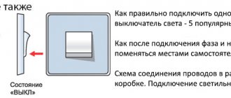
It is also not entirely clear what kind of pass-through, intermediate and cross switches and “two-way” switches these are. Let's figure out what the difference is between these devices.
We will try to write in a language accessible to everyone, so we ask you in advance not to find fault with the writing style, terms, etc.
Switch - a device, usually having two contacts, which, when turned on, connects the contacts (turns on the lamp), and when turned off
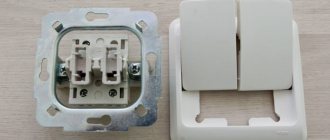
state, accordingly, disconnects the contacts (turns off the lamp). Everything here is very obvious and understandable. What the white switch looks like, article number 774401 series Valena (Valena), is shown on the reverse side in the photo on the right.
Manufacturers usually indicate with arrows which contacts are which. The arrows show that the “phase” conductor should be connected to the “input” (this is the arrow pointing to the center of the switch) of the switch, and the conductor going to the load (i.e., the light bulb) to the “output” (the arrow indicating the direction from the center of the switch). “Why should the switch be connected this way? It will work if you connect it the other way around!” - you ask. That’s right, it will work either way, but there are two nuances:
- For correctly mounted switches, when turned on, the key occupies the “up” position, and when turned off, the button occupies the “down” position. When connecting according to the diagram, if the phase conductor is connected to the “output” of the switch, and the “load” to the input, then the switch key will always be “upside down”. That is, when turned on, the key will occupy the “down” position, but should occupy the “up” position, and vice versa.
- When connected according to the diagram, the phase will first pass through the lamp and break at the switch (i.e., when the switch is off, the lamp will always be energized). And this is wrong! With the correct connection diagram, the “phase” in the off state is broken at the switch and there will be no voltage on the lamp (i.e., when you change a burnt-out lamp, you will not get an electric shock).
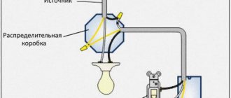
Figure 1. Switch connection diagram.
There are also two-pole switches that break not only the phase wire, but also the zero (neutral) conductor, but they, as a rule, are used only in specific cases.
A switch is a device that has three (or more) contacts. In the “On state” it closes the first and second contacts, and in the “Off state” it closes the first and third contacts. Essentially, the switch is always on - either in one state or the other.
Hence the name “Switch” - switches from one contact to another. If a switch only has two contacts, it will act like a switch.
In its catalogues, Legrand uses the concept of a "two-way switch" - this is what it is, because the switch switches between two contacts. In general, a switch can switch between three or more contacts, but in electrical installation mechanisms, if such occurs, it is extremely rare, so no one specifies how many directions the switches switch. Switches are also often called “pass-through switches,” but this concept, in our opinion, is incorrect and should not be used.
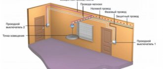
One of the most popular uses of a switch is to control lighting from two places. To control lighting you will need only two switches, and to control lighting from three or more places you cannot do without the use of pass-through (cross) switches.
Figure 2. Switch connection diagram.
Switches in our catalog:
- Internal installation - in the series: Celiane, Valena, Cariva, Mosaic.
- Wall mounting - in the series: Quteo, Oteo.
- Waterproof - in the series: Quteo, Plexo.
An intermediate (also known as cross) switch is a device that switches two separate lines crosswise (that is, if before the cross switch the phase was on the right and the zero on the left, then when switching they will switch places). The appearance of intermediate switches is no different from conventional switches. For clarity, see the diagrams in the pictures.
An intermediate switch is usually used to control lighting from three or more places.
This switch is called “cross” because it seems to cross the lines when switching, and it is called “Intermediate” because in the switching circuit when controlled from three or more places it is located in the gap between the “two-way switches”.
Figure 3. State diagrams of a pass-through switch.
Eleko - Online electrical store in Irkutsk www.eleko.pro
Mikhail, September 01, 2013
When using this article, a link to this page is required
Connection diagram
Typical connection diagrams
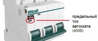
When purchasing cables for mounting a three-position device, it is necessary to take into account the maximum operating current values in the electrical circuit. If the diameter of the conductors exceeds 6 mm2, special tips are purchased for them. Less thick wires can be connected directly to the device using soldering or ring cutting.
Typical diagrams suitable for a particular device, including a diagram for connecting a switch from three different places, are given in the technical documentation accompanying it. Some of the three-position products can be connected not only to 3 poles, but also to 1, 2 or 4 (the possible number of poles is indicated in the device passport). At the entrance to the apartment, the device is placed at the point of tapping from the common phase conductor and zero in order to separate the apartment line from the main line. Installation of the switch and its subsequent adjustment can only be done when the electricity is turned off. Modern products designed for use in residential panels usually require installation on a 35 mm DIN rail. Their terminal clamps are marked with numbers, which avoids confusion during the installation process. After installation, the device, as well as adjacent contact connections, must be cleaned with a dry cloth at least once every 6 months, having first disconnected the power from the network.
Difference between switch and switch
All switches and switches serve one thing - to close or open an electrical circuit at the right time (turn on or off the lighting). These devices come in a variety of types and differ in design. In this article we will understand what switches and switches are and how they differ from each other.
- Definition
- Comparison
- Conclusions TheDifference.ru
Definition
A switch is a two-position switching device with normally open two contacts, designed for operation in networks with voltages up to 1000 V. The switch is not designed to disconnect short-circuit currents (short circuit) unless it has special arc extinguishing equipment. For a household switch, its design is very important - for internal installation (for hidden wiring, built into the wall) or for external installation (for open wiring, mounted on the wall). Switches are mainly used to turn lights on/off.
A switch (also known as a pass-through, changeover or backup switch) is a device that switches one or more electrical circuits to several others. Outwardly, it is almost no different from a switch, only it has more contacts. So, for example, a single-key switch has three contacts, a two-key switch has six (represents two independent single-key switches).
Comparison
Unlike a switch, where the electrical circuit is simply interrupted, when you press the switch key, switching occurs from one contact to another. And instead of interrupting the electrical circuit, the contacts are switched and a new circuit is created (that’s why switches are also called changeover switches). This feature allows you to manipulate the same light source from different points using a switch. A system consisting of several switches (changeover switches) is called a pass-through switch.
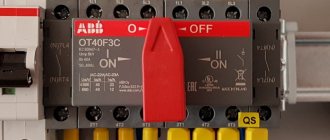
EMAS switch (3 positions)
Practical recommendations for use
Using the switch requires compliance with the following rules:
- The device is operated at temperatures from -40 to +50 degrees.
- The reversing switch is installed only in a panel with a mounting panel.
- It is allowed to manually activate circuit breakers with arcing and breaking contacts.
- The burnt contact blade is cleaned with a file or glass paper.
- To prevent the legs from skewing, tighten the mounting bolts tightly.
- All active parts of the device are isolated.
- For manual phase transfer, a transition switch operating in two directions is suitable.
- You need to select a switch according to the power of the current passed.
Changeover switches are suitable for installation in apartment buildings, in production with backup generators. The devices simplify the maintenance of power supplies, monitor power lines and protect the equipment connected to it.
Batch switches and switches
Packet switch device
A batch switch consists of a switching mechanism and a contact group. The fixed contact terminals protrude from the housing. The moving contacts are located inside the housing on a square bushing made of insulating material. The body is assembled from insulating washers connected to each other by tightening pins. The moving contacts are turned by hand through a spring-loaded quick switch mechanism.
When you turn the handle, the spring of the quick shift mechanism is wound up first. When the force acting from the handle on the shaped washer increases to a certain value, the washer very quickly turns a quarter turn to the next stop in the top cover.
The stops in the cover are located at an angle of 90°. A square bushing, on which the movable contacts are mounted, is connected to a shaped washer. Simultaneously with the rapid rotation of the figured washer, the movable contacts rotate. The latter are reinforced in fiber plates, which act as guides and ensure rapid extinguishing of the emerging arc.
Fiber releases large amounts of gases when exposed to high temperatures. Their pressure increases, resulting in the movement of gases through the cracks of the bag. Fresh, non-ionized air entering the circuit breaker helps to quickly extinguish the arc.
Package switches are produced for currents of 10 and 25 A at a voltage of 220 V in one-, two- and three-pole versions. The latter are used to switch on three-phase asynchronous motors (for example, in universal drives). In a three-pole stack switch, three moving contacts are located between four insulating washers. The same package switches can also be used at a voltage of 380 V, but the permissible current value for them is reduced to 6 and 15 A, respectively.
At rated current and voltage values and a power factor of 8.0, package switches can withstand 20,000 switching operations. The switching frequency should not exceed 300 per hour.
For the convenience of connecting wires, the fixed contacts are not located along a generatrix, but are shifted relative to each other. The terminals of one contact are located between the same washers diametrically opposite. It is customary to connect the wires from the receiver to the terminals located on one side of the studs, and the network wires to the other.
By turning the batch switch handle 90°, you can turn the receiver on and off. Of the four positions of the packet switch handle, two correspond to the on and two to the off state of the receiver.
In addition to packet switches, packet switches are also widely used. In a packet switch, only one position corresponds to the disabled state of the receiver, and the other three correspond to the enabled state in various ways.
The figure shows a diagram for switching on a three-speed motor M with a packet switch Q. The four-position packet switch has six moving contacts. One position (0) corresponds to the engine off state. The motor stator has two windings, one of which is star connected and the other can be switched from delta to double star.
Scheme for switching on a three-speed electric motor with a packet switch
According to the diagram, in position 1 of the handle, the motor is connected to the network using terminals ZS1, ZS2, ZSZ. A rotating magnetic field with three pairs of poles is created in the motor stator. The synchronous engine speed (magnetic field speed) is 1000 rpm.
The connection of the left terminals of the switch with the right ones is indicated by dots with lines depicted vertically under the numbers corresponding to the positions of the switch handle. In position 1 of the switch handle, the upper left terminal is connected to terminal 3S1 of the motor, the middle left terminal is connected to terminal ZS2, and the lower left terminal is connected to terminal ZSZ.
In position 3 of the handle, along with the connection of the left terminals of the switch with terminals 1С1, 1С2, 1СЗ of the engine, terminals 2С1, 2С2 and 2СЗ are connected to each other. This ensures that the winding is connected in a double star, forming one pair of poles and obtaining a synchronous rotation speed of 3000 rpm.
In position 2 of the switch handle, the top left terminal is connected to terminal 2C1 of the motor, the middle left terminal is connected to terminal 2C2, and the bottom left terminal is connected to terminal 2SZ. In this case, the motor is switched into a triangle with the formation of two pairs of poles and obtaining a synchronous rotation speed of 1500 rpm.
Three Pole Batch Switch
It differs from a three-pole switch in that the moving contacts (knives) have not one, but two closed positions. The knives can be locked with three left and three right fixed contacts. Such switches are used to turn on three-phase motors and change the direction of their rotation (reversing), a three-phase motor is achieved by switching two current-carrying wires.
What is the difference between a switch and a switch?
A correctly connected pass-through switch allows you to control lighting from two or more places, which is very convenient.
For example, there is a long corridor in the house; by turning on the light at the beginning, you can turn off the light at the end of the corridor with the second switch. Quite often, such schemes are used to control the lighting of stairs. Let's consider a typical lighting control scheme from two places.
By pressing the key of any switch, you can turn the lamp on or off independently of the second switch.
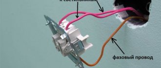
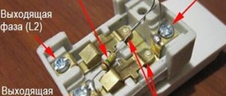
Implementing a lighting control scheme from two places is not difficult, despite its apparent complexity. The main thing is to find the common terminal on the switch, that is, the one that does not switch. Typically, this terminal is marked in red, the letter L, or the number 1.
Having identified these terminals, we connect the phase wire to them on one switch, and on the second the wire coming from the light bulb. The remaining two terminals on the switches are connected to each other in any order. The neutral wire comes to the light bulb according to the circuit directly from the junction box.
Legrand pass-through switch connection diagram.
The lighting control circuit from three places is not much different from the previous one, it adds another cross switch (it is also sometimes called an intermediate switch), which has four wire connection terminals. As the name suggests, when a key is pressed, two independent electrical lines are simultaneously switched crosswise.
The presented circuit will work if the number of intermediate switches increases. Thus, using the presented scheme, you can control lighting from three or more places.
Scheme of a pass-through switch with control from three places.
A two-key pass-through switch allows you to separately control two independent lines of lamps or one chandelier with separate lamp switches.
Structurally, a two-key pass-through switch consists of two single-key pass-through switches combined in one housing. When connecting, be careful not to confuse the contacts, otherwise the circuit will not work.
Connection diagram for a pass-through two-key switch Legrand.
Related materials:
Differences
These devices differ in operating principles
, so they are used in different situations. Among the most characteristic features of switches and switches, it is necessary to highlight the following:
- The switch is characterized by the presence of only two contacts
. Its work is expressed in connecting and disconnecting an electrical circuit. This is how the light is turned on and off. Meanwhile, the switch has more advanced capabilities. It is capable of connecting and disconnecting an electrical circuit, that is, performing the functions of a switch. But in addition to this, the switch can also create a new electrical circuit. This is achieved due to the presence of three contacts. - Switches are installed in the appropriate rooms and are used to turn on or off lighting fixtures that are located in the same room. In this case, using switches, you can control the same lighting fixture from several places. An example is the control of lamps in a corridor. When entering the corridor, you can use the switch to turn on the light. And after walking along it and finding yourself at the end of the corridor, using another switch you can turn off the light.
- In order to be able to turn lighting on or off from three or even more different points, so-called pass-through switches
. In this case, one single-key switch should be installed closer to the beginning and to the end of the electrical circuit. And between them you can install any number of transition switches.
Thus, the switch is a more functional product
. It is great for cases where a fairly large space is illuminated. This could be a long corridor or several flights of stairs. Thanks to the capabilities of switches, it will be possible to control the operation of lighting fixtures along the entire electrical circuit from anywhere.
Moreover, such places can be determined by the customer himself when performing electrical installation work. That is, it will be possible to create a simple, reliable and comfortable lighting control system. At the same time, the fundamental difference between switches and switches lies precisely in the number of contacts. This value determines the wider useful capabilities of the switches.
How to connect a pass-through switch
If you use pass-through switches, it is possible to control one light source from two, three or more places. Let's look at what options there are for connecting pass-through switches.
We connect two-key pass-through switches
This method is necessary if there is a long corridor. Entering it, you turn on the light; when you reach the end, you need to turn off the light. This is where the connection diagram for two pass-through switches is used.
Connection diagram for two-button switch
It is necessary to switch the reversible view, i.e. On one side of the corridor the contacts close, on the other they open. To do this, we install a junction box from which two cables come out - neutral and power, respectively, neutral goes to the first switch, power - to the second. The phase wire in this case is connected through a box with two switch contacts at the end of the corridor, and this phase is transferred to the lamp.
Connection diagram for two-button switch
There are also double pass-through touch switches. There is nothing difficult about how to connect a model with a dimmer. These devices are controlled from a 30 meter distance. The sensor wires are connected to an open in the lamp control circuit. In turn, the installation of the touch switch box itself is practically no different from the usual one. One wire goes to negative, the other to phase. Before installing remote pass-through switches, you need to determine which contacts go to the luminaire and which to the command block or branch box, and combine them into certain groups.
Triple switches
There are no fundamental differences in how to connect Legrand pass-through switches for three-seat control from the method outlined above. You need to use a paired type of switch and four-wire wires. Using a paired switch, the contacts from one device are transferred to the other two.
Scheme of a cross coupled switch
Single triple switches have three contacts - two inputs and one output. The neutral wire from the power cable goes to the light source. The output contacts are connected to the second pass-through switch, and the third contact goes to the power supply.
Single triple switches
In addition, you can connect a special remote control to any of these circuits, which works wirelessly. You can use absolutely any device to turn on equipment at a distance with a power of up to 1.5 kW in order to turn off the lighting at a certain distance. To do this, we connect a relay to the remote control, point it towards the lamp and press a certain button, which we will then use as a command button. After this, the operation is recorded in volatile memory and now when you press this particular button, the light will turn on or off, regardless of whether the remote control is connected to the relay or not. In this case, the lighting control locations are not limited.
Two-gang switches
These devices have the ability to control six light sources simultaneously. The design solution is made in such a way that there are 2 separate switches in one housing. They can be connected in the following ways:
- 3 contacts or single method;
- paired or cross method (for connecting 4 or more lamps).
Different circuits for connecting switches
We buy pass-through cross switches
Before you connect pass-through light switches, you need to select the devices to suit your needs. Touch switches have from one to four contact zones, thanks to which up to four light sources can be controlled with one device. Such models are devices from lezard, viko and makel.
If conventional overhead electrical switches are used, two-wire devices from Schneider Electronics and Abb are recommended. Despite the fact that the price of these devices is slightly lower. They are no different in quality than the above companies.
What you need to know before buying pass-through switches:
- number of light sources;
- arrangement of lamps: parallel or sequential;
- voltage strength of the apartment's power supply network.
The number of installation locations from which you can control the light is unlimited; any electrician will confirm this. The installation of switches is carried out according to all the rules: sealing contacts, installing grounding, connecting to an RCD.
Cross disconnect principle
A crossover switch is similar to a regular single-key switch, the only difference being the presence of four terminals inside. The crossover is named because the two electrical lines it switches are connected into a cross.
The cross disconnector simultaneously disconnects the first and second switches, then connects them synchronously. This movement of the contacts causes the light to turn on and off.
Advice! Pay special attention to the correct connection of the ends of the electrical cables, otherwise the entire system will not work. The number of points may vary, but the more there are, the more difficult the switching in the distribution box. It is necessary to clearly mark the wires when conducting them so as not to confuse them.
Installation of switches
Operating diagram of a pass-through switch
We go into the room and turn on the light. Switches do an excellent job of this task. What could be simpler? However, switches differ greatly from each other, both in design, functionality and installation method. The device is made of high-quality impact-resistant plastic with smooth surfaces. Switches are installed in easily accessible places and operate in open and hidden electrical wiring circuits. The design of the devices is varied. There are classic products that are not subject to fashion trends. There are models that add individual features to the interior. The color palette of switches can satisfy the most sophisticated taste. Strict (white or black), various colors and shades. Therefore, achieving a combination with wallpaper, wood paneling or furniture is a completely solvable task. Many companies produce products with decorative replaceable panels. After installing the switch, various linings can be easily installed on the mounted mechanism. Now let's talk about functionality and consider connection diagrams for conventional and pass-through switches (switches). Switches can be single, double or triple. Can be installed in blocks to solve complex lighting problems and advanced lighting control. If the technical specifications require switching on one light group from two or more places, pass-through switches (switches) are installed. Connection diagrams are given below.