An electric motor is a mechanism that converts the energy of electric current into kinetic energy. It is difficult to imagine modern production and everyday life without electrically driven machines. They are used in pumping equipment, ventilation and air conditioning systems, electric vehicles, industrial machines of various types, etc.
When choosing an electric motor, you must be guided by several basic criteria:
- the type of electric current powering the equipment;
- electric motor power;
- operating mode;
- climatic conditions and other external factors.
Engine types
DC and AC motors
Depending on the electric current used, motors are divided into two groups:
- DC drives;
- AC drives.
DC motors are not used as often today as they used to be. They have practically been replaced by asynchronous motors with squirrel-cage rotors.
The main disadvantage of DC electric motors is that they can only be operated with a DC source or an AC-to-DC converter. In modern industrial production, ensuring this condition requires additional financial costs.
However, with significant disadvantages, this type of motor is characterized by a high starting torque and stable operation under conditions of high overloads. Drives of this type are most often used in metallurgy and machine tool construction and are installed on electric vehicles.
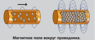
The operating principle of AC electric motors is based on electromagnetic induction that occurs during the movement of a conducting medium in a magnetic field. To create a magnetic field, windings flowing around currents or permanent magnets are used.
AC electric motors are divided into synchronous and asynchronous. Each subgroup has its own design and operational features.
Synchronous electric motors
Synchronous motors are the optimal solution for equipment with constant operating speed: DC generators, compressors, pumps, etc.
The technical characteristics of synchronous electric motors of different models differ. The rotation speed ranges from 125 to 1000 rpm, the power can reach 10 thousand kW.
The design of the drives includes a short-circuited winding on the rotor. Its presence allows for asynchronous engine starting. The advantages of equipment of this type include high efficiency and small dimensions. The operation of synchronous electric motors allows you to reduce electricity losses in the network to a minimum.
Asynchronous electric motors
Asynchronous AC motors are most widely used in industrial production. A feature of these drives is a higher frequency of rotation of the magnetic field compared to the speed of rotation of the rotor.
Modern engines use aluminum to make the rotor. The light weight of this material makes it possible to reduce the weight of the electric motor and reduce the cost of its production.
The efficiency of an asynchronous motor drops almost by half when operating at low loads - up to 30-50 percent of the nominal value. Another disadvantage of such electric drives is that the starting current parameters are almost three times higher than the operating parameters. To reduce the starting current of an asynchronous motor, frequency converters or soft starters are used.
Asynchronous motors meet the requirements of various industrial applications:
- For elevators and other equipment requiring stepwise speed changes, multi-speed asynchronous drives are produced.
- When operating winches and metalworking machines, electric motors with an electromagnetic braking system are used. This is due to the need to stop the drive and fix the shaft in case of power outages or disappearance.
- In processes with a pulsating load or in intermittent modes, asynchronous electric motors with increased sliding parameters can be used.
Valve motors
The group of valve electric motors includes drives in which the operating mode is controlled by means of valve converters.
The advantages of this equipment include:
- High service life.
- Easy maintenance due to contactless control.
- High overload capacity, which is five times the starting torque.
- Wide speed control range, which is almost twice the range of asynchronous electric motors.
- High efficiency at any load - more than 90 percent.
- Small dimensions.
- Fast payback.
Electric motors with electromagnetic brake
An electric drive with an electromagnetic brake is designed for operation in intermittent or short-term mode. It is designed specifically for mechanisms that require forced stopping at strictly regulated times. Such mechanisms include: electric hoists, automated warehouse systems, processing machines, etc. The brake mechanism, as a rule, is located on the side opposite to the motor shaft. It provides rapid braking of the electric drive when the power is turned off, and when the voltage is reapplied, it releases the brake.
Electric machines with a built-in electromagnetic brake operate according to the following principle:
- The electromagnetic brake coil is connected in series to one of the phase windings of the electric motor.
- The coil receives direct voltage through a rectifying device, which is located near the terminal box, or alternating voltage directly from the motor winding.
- In the absence of phase voltage, the coil is de-energized, and the armature firmly clamps the locking mechanism.
- After the electrical power is restored, the coil pulls the armature, which allows the motor shaft to move freely.
Depending on the installation method, electric motors with a built-in electromagnetic brake are manufactured in the following versions:
- With horizontal shaft.
- With vertical shaft.
Due to its advantages in stopping time of the motor shaft, this type of electric drive ensures reliable and safe operation of devices with high positioning or emergency stop requirements.
Motor power
A large number of mechanisms operate in constant or slightly varying load mode: fans, compressors, pumps, and other equipment. When choosing an electric motor, you need to focus on the power consumed by the equipment.
Power can be determined by calculation using the formulas and coefficients given below.
The power on the electric motor shaft is determined by the following formula:
where: Рм – power consumed by the mechanism; ηп — transmission efficiency.
It is advisable to choose the rated power of the electric motor greater than the calculated value.
Formula for calculating electric motor power for a pump
where: K3 - safety factor, it is equal to 1.1-1.3; g—gravitational acceleration; Q—pump performance; H—lift height (calculated); Y is the density of the liquid pumped by the pump; ηus - pump efficiency; ηп — transmission efficiency.
Pump pressure is calculated using the formula:
Formula for calculating electric motor power for a compressor
The power of a piston compressor can be easily calculated using the following formula:
where: Q - compressor performance; ηk is the indicator efficiency of the piston compressor (0.6-0.8); ηп - transmission efficiency (0.9-0.95); K3 - safety factor (1.05 -1.15).
The value of A can be calculated using the formula:
or take it from the table
| p2, 105Pa | 3 | 4 | 5 | 6 | 7 | 8 | 9 | 10 |
| A, 10–3 J/m³ | 132 | 164 | 190 | 213 | 230 | 245 | 260 | 272 |
Formula for calculating motor power for fans
where: K3 is the safety factor. Its values depend on engine power:
- up to 1 kW - coefficient 2;
- from 1 to 2 kW - coefficient 1.5;
- 5 kW or more - coefficient 1.1-1.2.
Q—fan performance; H—outlet pressure; ηв — fan efficiency; ηп — transmission efficiency.
The given formula is used to calculate the power of axial and centrifugal fans. The efficiency of centrifugal models is 0.4-0.7, and that of axial fans is 0.5-0.85.
The remaining technical characteristics necessary to calculate engine power can be found in the catalogs for each type of mechanism.
Important! When choosing an electric motor, there should be a power reserve, but it should be small. With a significant power reserve, the drive efficiency decreases. In AC motors, this also leads to a decrease in power factor.
Electronics for everyone
After the previous post about the gear motor, I received several questions about regulating a DC motor. So it's time to write another post
The direct current motor (DC motor) is one of the most familiar and understandable electric motors; it is studied even in school, in physics. It is used almost everywhere where a small-sized motor is needed, and is also in no hurry to lose its position even where power is measured in tens of kilowatts. Let's talk about him. ▌ Design and basic principle
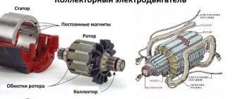
I won’t go into too much detail here, I’ll show you a picture from Wikipedia and indicate a number of main components. Everything else you already know and have touched with your own hands.
1. The stator consists of a magnetic field source. This is not always a permanent magnet; moreover, a permanent magnet is the exception rather than the rule. Usually this is the excitation winding. At least on anything larger than a fist.
2. The armature consists of an armature winding and a collector unit.
Everything works very, very simply. The armature winding is repelled from the magnetic field of the stator by the Ampere force and makes half a revolution, trying to bring this force to zero and would have brought it out if not for the collector, which cleverly breaks off everyone, switches the polarity of the coil and the force again becomes maximum. And so on in a circle. Those. the collector serves as a mechanical voltage inverter in the armature. Remember this moment, it will be useful to us later
Usually in small motors there are only two poles of the field winding (one pair) and a three-prong armature. Three teeth is the minimum for starting from any position, but the more teeth, the more efficiently the winding is used, the lower the currents and the smoother the torque, since the force is a projection onto the angle, and the active section of the winding rotates to a smaller angle
▌Processes occurring in the engine
I think many of you who have dabbled with engines may have noticed that they have a pronounced starting current, when the motor at the start can jerk the ammeter needle, for example, to an ampere, and after acceleration the current drops to some 200 mA.
Why is this happening? This is how back emf works. When the engine is stopped, the current that can pass through it depends only on two parameters - the supply voltage and the resistance of the armature winding. So it’s easy to find out the maximum current that the engine can develop and for which the circuit should be calculated. It is enough to measure the resistance of the motor winding and divide the supply voltage by this value. Simply by Ohm's law. This will be the maximum starting current.
But as it accelerates, a funny thing begins: the armature winding moves across the magnetic field of the stator and an EMF is induced in it, like in a generator, but it is directed opposite to the one that rotates the engine. And as a result, the current through the armature decreases sharply, the more, the higher the speed.
And if the engine is further tightened along the way, then the back emf will be higher than the supply and the engine will begin to pump energy into the system, becoming a generator.
▌A few formulas
I won’t burden anyone with conclusions; you’ll find them yourself if you want. To make it less profane, I recommend finding a textbook on electric drives for secondary schools and an older year of publication. It’s from the 50s-60s. There are vintage pictures and painted for yesterday’s graduate of a rural seven-year school. Lots of letters and no sinkers, everything is clear and to the point.
The most important formula for a brushed DC motor is:
U = E + I*Rya
- U - voltage supplied to the armature
- Rya is the resistance of the anchor chain. Usually, only the resistance of the winding is considered as this symbol, although you can hang a resistor on the outside and it will be added to it. Then they write it as (Rа+Rд)
- Iya is the current in the armature circuit. The same one that is measured with an ammeter when trying to measure engine consumption
- E is the back emf or emf of the generator, in generator mode. It depends on the engine design, speed and is described by this simple formula
E = Ce * F * n
- Ce is one of the design constants. They depend on the design of the motor, the number of poles, the number of turns, and the thickness of the gaps between the armature and the stator. We don’t really need it; if desired, it can be calculated experimentally. The main thing is that it is constant and does not affect the shape of the curves
- F is the excitation flux. Those. stator magnetic field strength. In small motors, where it is set by a permanent magnet, this is also a constant. But sometimes a separate winding is brought out for excitation and then we can change it.
- n - armature revolutions.
Well, the dependence of torque on current and flow:
M = cm * Iа * F
Cm is a constructive constant.
Here it is worth noting that the dependence of torque on current is completely direct. Those. Simply by measuring the current, with a constant excitation flux, we can accurately determine the magnitude of the torque. This may be important, for example, in order not to break the drive, when the engine can develop such a force that it can easily break what it rotates there. Especially with a gearbox.
Well, it follows from this that the torque of a DC machine depends only on the ability of the source to supply it with current. So the ideal indestructible superconducting engine will tie you in knots, even if it’s as small as a nail. Just supply energy.
Now let’s mix it all together and get the dependence of revolutions on torque - a mechanical characteristic of the engine.
If you build it, it will be something like this:
n0 is the ideal idle speed of a spherical engine in a vacuum. Those. when our engine is finally freezing, the torque is zero. The current consumption is also, naturally, zero. Because back emf is equal to voltage. Purely theoretical option. And the second point is constructed with some moment on the shaft. It turns out there is a direct relationship between speed and torque. And the slope of the characteristic is determined by the resistance of the armature chain. If there are no additional resistors there, then this is called a natural characteristic.
Ideal idle speed depends on voltage and flow. Nothing else. And if the flux is constant (permanent magnet), then only from voltage. By reducing the voltage, our entire characteristic shifts down in parallel. Reduced the voltage by half - the speed dropped by half.
If it is possible to change the excitation flow, then you can raise the speed above the nominal one. Here the relationship is reversed. We weaken the flow - the engine accelerates, but either the torque drops, or it needs to consume more current.
Another engine with excitation removed may go into disarray. I remember I took a long course on electric drive, who knows how long after the session. I had to break it, yeah. Well, I sat in the laboratory, waiting for the teacher. And there were some dunces, a course lower, who made a lab. They turned the engine idle, and the excitation was attached to the stand on snot and flew off the terminal. The engine went haywire. In our laboratory at EPA SUSU, everything was serious, the machines were serious, ten kilowatts and about a hundred or so kg each. Everything is at a harsh voltage of 380 volts. In general, when this fool roared like a monster and began to tear itself from its mounts, all I had time to shout was to get the hell out of the car, turn it to hell. Before we had time, the engine was torn from its mounts, the windings flew out of the grooves and the engine suffered damage. Okay, no one was hurt. However, the drive labs were still entertainment. We had fires and explosions there. There I acquired remarkable skills to fix anything, with anything, in a short time. On average, everyone managed to completely kill the stand once, and the lab often began with repairing the soldering iron, which was used to repair the oscilloscope, with the help of which the dead stand was reanimated.
By adding resistors to the armature circuit we can increase the slope, i.e. The more we load, the more the speed drops.
The method is bad because the resistors in the armature circuit must be rated for the motor current, i.e. be powerful and will heat up in vain. Well, the moment drops sharply, which is bad.
There are also motors with sequential rather than independent excitation. This is when the stator winding is connected in series with the armature. Not every motor can be turned on this way; the field winding must withstand the armature current. But they have one interesting property. When starting, a large starting current occurs and this starting current is also the excitation current, providing a huge starting torque. The mechanical characteristic resembles a hyperbola with a maximum in the region of zero revolutions.
And then, as you accelerate, the torque drops, and the speed, on the contrary, increases. And if the load is removed from the shaft, the engine immediately goes into overdrive. Such engines are mainly installed on a draft drive. At least they did before, before the development of power electronics. This crap explodes from its place so much that all the street slayers nervously light up.
▌DC motor operating modes
The direction of rotation of the motor depends on the direction of the armature current or the direction of the excitation flow. So if you take a commutator motor and connect the excitation winding parallel to the armature, then it will rotate perfectly on alternating current (universal motors, they are often installed in kitchen appliances). Because the current will simultaneously change in both the armature and the excitation. The moment will indeed be pulsating, but these are minor things. And to reverse it, you will need to change the polarity of the armature or excitation.
If we draw a mechanical characteristic in four quadrants, we will have something similar to this:
For example, characteristic 1 in section I, our car works like an engine. The load increases and at a certain moment the engine stops and begins to rotate in the opposite direction, i.e. the load reverses it. This is a braking mode, anti-inhibition. The mode is very difficult, the engine heats up simply brutally, but it is very effective for braking. If the moment on the shaft changes direction and starts to rotate towards the engine, then the motor will immediately go into generation (section IV).
Characteristic 2 is the same, only with reverse polarity of the motor supply voltage.
And characteristic 3 is dynamic braking. It's rheostat. Those. when we take and simply short-circuit our motor to a resistor or to itself. You can check it yourself, take any motor and spin it, and then short-circuit its armature and spin it again. There will be a noticeable force on the shaft, the greater the quality of the engine.
By the way, motor drivers like the L293 or L297 have the ability to turn on rheostatic braking by turning both keys up or down. In this case, the armature shorts through the driver to the ground or power bus.
▌Brushless DC Motors
The collector engine is very good. It's damn easy and flexible to adjust. You can increase the speed, lower it, the mechanical characteristics are tough, it holds the torque with a bang. The dependence is direct. Well, it's a fairy tale, not a motor. If it weren't for one spoonful of shit in all this deliciousness - a collector.
This is a complex, expensive and very unreliable unit. It sparks, creates interference, and becomes clogged with conductive dust from the brushes. And under heavy load it can blaze, forming a circular fire, and then that’s it, the engine is screwed. It will short-circuit everything tightly.
But what is a collector anyway? Why is he needed? Above I said that the collector is a mechanical inverter. Its task is to switch the armature voltage back and forth, exposing the winding to the flow.
But it’s already the 21st century and cheap and powerful semiconductors are now at every turn. So why do we need a mechanical inverter if we can make it electronic? That's right, there's no need! So we take and replace the collector with power switches, and also add rotor position sensors so that we know at what moment to switch the windings.
And for greater convenience, we turn the engine inside out - it’s much easier to rotate a magnet or a simple excitation winding than an armature with all this junk on board. The rotor here is either a powerful permanent magnet or a winding powered by slip rings. Which, although it looks like a collector, is far more reliable than it.
And what do we get? Right! Brushless DC motor aka BLDC. All the same cute and convenient characteristics of the DPT, but without this nasty collector. And do not confuse BLDC with synchronous motors. These are completely different machines and have different principles of operation and control, although structurally they are VERY similar and the same synchronizer can easily work as a BLDC, adding only sensors and a control system. But that's a completely different story.
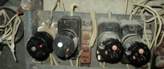
Motor starting current
Knowing the type and rated power of the electric motor, you can calculate the rated current.
Rated current of DC motors
Rated current of three-phase AC motors
where: PH is the rated power of the electric motor; UH is the rated voltage of the electric motor, ηH is the efficiency of the electric motor; cosφH is the power factor of the electric motor.
Rated power, voltage and efficiency values can be found in the technical documentation for a specific electric motor model.
Knowing the value of the rated current, you can calculate the starting current.
Formula for calculating the starting current of electric motors
where: IH - rated current value; Kp - direct current multiple to the rated value.
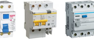
The starting current must be calculated for each motor in the circuit. Knowing this value, it is easier to select the type of circuit breaker to protect the entire circuit.
By synchronization:
• Synchronous motor
– AC electric motor with synchronous movement of the magnetic field of the supply voltage and the rotor.
• Asynchronous electric motor
– an alternating current electric motor with a different frequency of rotor movement and a magnetic field generated by the supply voltage.
See also:
- Volkswagen New Beetle
- Opel Ascona A
- Daewoo Lanos
- History of the road sign
- BMW E65-E66
- Airless tires
- BMW Z8
Operating modes of electric motors
The operating mode determines the load on the electric motor. In some cases it remains virtually unchanged, in others it may change. The nature of the expected load must be taken into account when choosing an engine. Current standards provide for the following operating modes:
Mode S1 (long-term). In this operating mode, the load remains constant for the entire time until the temperature of the electric motor reaches the required value. Drive power is calculated using the formulas given above.
Mode S2 (short-term). When operating in this mode, the engine temperature during its switching on does not reach the steady-state value. During shutdown, the electric motor cools down to ambient temperature. During short-term operation, it is necessary to check the overload capacity of the electric drive.
Mode S3 (periodically-short-term). The electric motor operates with periodic shutdowns. During periods of switching on and off, its temperature does not have time to reach the set value or cool down to the ambient temperature. When calculating engine power, the duration of pauses and losses during transition periods must be taken into account. When choosing an electric motor, an important parameter is the permissible number of starts per unit of time.
Modes S4 (periodically short-term, with frequent starts) and S5 (periodically short-term with electric braking). In both cases, the engine operation is considered according to the same parameters as in operating mode S3.
Mode S6 (periodically-continuous with short-term load). Operation of the electric motor in this mode involves operation under load, alternating with idling.
Mode S7 (intermittent-continuous with electric braking)
Mode S8 (periodically-continuous with simultaneous change in load and rotation speed)
Mode S9 (mode with non-periodic changes in load and rotation speed)
Most models of modern electric drives, which have been in operation for a long time, are adapted to changing load levels.
Climatic versions of electric motors
When choosing an electric motor, not only its technical characteristics are taken into account, but also the environmental conditions in which it will be operated.
Modern electric drives are available in different climatic versions. Categories are marked with corresponding letters and numbers:
- U - models for use in temperate climates;
- HL - electric motors adapted to cold climates;
- TS - versions for dry tropical climates;
- TV - versions for humid tropical climates;
- T - universal versions for tropical climates;
- О - electric motors for operation on land;
- M - engines for operation in marine climates (cold and temperate);
- B - models that can be used in any area on land and at sea.
The numbers in the model nomenclature indicate the type of its placement:
- 1 — possibility of operation in open areas;
- 2 — installation in rooms with free access of air;
- 3 — operation in closed workshops and premises;
- 4 — use in industrial and other premises with the ability to regulate climatic conditions (availability of ventilation, heating);
- 5 — versions designed for operation in areas of high humidity, with high condensation formation.
Energy efficiency
Efficient energy consumption while maintaining high power reduces ongoing operating costs while increasing motor performance. Therefore, when choosing a drive, the energy efficiency class must be taken into account.
Technical documentation and catalogs must indicate the energy efficiency class of the engine. It depends on the efficiency indicator.
Experimental studies carried out in test and operating modes show that a 55 kW electric motor of high energy efficiency class reduces electricity consumption by 8-10 thousand kW annually.