Types of breakdowns and their causes
Typical breakdowns: partial or complete absence of lighting, short-term blinking or spontaneous shutdown, failure.
Reasons : The temperature reached above 50 degrees, the contact between the filament itself and the holder broke, if the paid version is not a lamp version, the contacts on the board peeled off.
The LED has burned out, partially or completely. Reason : Overvoltage in the network, capacitor burnt out (breakdown). Typically, failure occurs in cheap board options.
There are additional reasons leading to device failure, namely: a short circuit in the circuit, incorrect connection to the network, non-compliance with the device connection diagram during installation.
Poor soldering of circuit contacts, LEDs to the board, weak fastening of wires in the base of the lamps. Poor soldering of conductive elements (wires, busbars). Reason : Factory defect. Many LED chandeliers with remote control are repaired precisely for this reason.
What else could it be
People never notice how many times a day they turn on and off the light bulbs in a chandelier. But this has a significant impact on the lifespan of LED lamps. Although manufacturers do not make any restrictions on this issue on the packaging.
Illuminated switches are convenient to use. They are easy to find in the dark, but they are also beautiful. They are the reason why light bulbs flicker or dim when turned off. This behavior of the light bulbs will also lead to a reduction in service life. The solution to the problem is to turn off the backlight or replace the switch.
It is rare, but 12 W LEDs burn out. The reason may be an incorrect connection diagram or an incorrectly selected power supply.
If all the 12 W light bulbs stop lighting at once, then this is a problem with the power supply.
Interesting video on the topic:
Preparation for repair of LED devices
Before repairing an LED lamp, the device must be removed. You will need some tools; a thin screwdriver with a flat end, cross-shaped. If the connection was made using twists, you will need pliers with insulated handles, insulating tape and a multimeter to check the contacts. Tweezers are useful when working with small parts.
You will need a soldering iron with a thin tip and solder (it is advisable to use a special nozzle). A drill with a 2.5 mm drill can also be useful to disconnect the base part of the lamp by drilling out the fasteners. Several thin wires, 10 cm long. Attention! It is prohibited to carry out electrical work without special protected tools!
Design of LED chandeliers and visual inspection
Chandeliers with remote control appeared not so long ago. Few people are familiar with their device. When repairing LED ceiling chandeliers, you need to know the design, just in general terms. Let's take a closer look at what it may consist of.
A simple LED chandelier consists of a housing, a controller unit or a driver. It is used as a voltage rectifier. It contains terminals, or terminal clamps, to which the mains power is connected. Then wires run from the block to the lamps. There can be from one wire, for a regular lamp, to 12 for a designer version of the device.
A more complex version of the product consists of an antenna, a control unit for the lighting itself, a voltage regulator or several units that perform automatic adjustment. Raster lamps can have several drivers and different types of LED elements and lamps. The inspection and repair of components depends on the specific type of lighting fixture.
Why you need to know or find out the design before you start repairing an LED chandelier. The reason is simple, you need to determine where the control units are located, inside the chandelier or in the lighting element itself, the lamp. Here we need the same LED chandelier circuit.
Repairing an LED chandelier operating without a remote control is easier. There is nothing complicated in it, they are assembled according to one type: one or more diodes (a compact bridge is possible), electrolytes (capacitors), a pair of resistances (resistors), and a coil with a winding. This is the simplest scheme without protection, there are many options, but now we will analyze the simplest scheme.
- After removing the lamp, inspect the board for the presence of visible defects, broken wires; the absence of such is a good sign.
- Remove the shade or decoration around the lamp, and unscrew the lighting elements. Inspect the base; burnt areas indicate poor contact. If there are any, try clearing them with a knife.
- Repack the terminal blocks or twists, tighten the screws on all parts. Having found no visible defects, we move on to inspecting the lamps. A variant of a block lamp, where the relays and lamps are located next to each other on a large board, is considered as a repair of the lamp described below.
- Repairing an LED chandelier with your own hands begins with determining the location of the breakdown or break.
Arrangement of linear LED lamps
A new generation of lamps has appeared on sale, similar in overall dimensions and appearance to lamps with fluorescent lamps. However, instead of fluorescent fluorescent lamps, they use LEDs. The lamps are economical, durable, but still quite expensive.
The industry has mastered the production of alternative LED lamps, in terms of overall dimensions, appearance and brightness, fully corresponding to fluorescent lamps. They use LEDs as a light source. The service life of LED analogues is tens of times longer and their disposal is not required. Thanks to the availability of LED analogues of fluorescent lamps, it is possible to save money - without buying new generation lamps, replace only the fluorescent lamps with LEDs in outdated lamps with your own hands, leaving the old fittings. Remaking old fluorescent lamps does not require high qualifications from the performer and, provided there are instructions, any home craftsman can do it with his own hands.
An LED lamp tube is a transparent plastic tube in which a getinax strip with LEDs soldered on it and a driver are installed. Therefore, the LED tube light does not need to install an external driver. It connects directly to the 220 V electrical network.
LED lamp tubes, like fluorescent tubes, have a G13 base. On the inside of the LED lamp tube, the pins are connected to each other by a piece of copper wire, so the supply voltage can be applied to any of the pins. The LED lamp tube is fully adapted to replace fluorescent lamps in luminaires without mechanical modification of their design. It is enough to just do a little work to change the wiring - remove the unnecessary ones.
LED tubes are available in lengths of 600 mm and 1500 mm, power from 9 to 25 W, cold and warm light and save at least 65% of electricity compared to fluorescent lamps. For example, an 18 W LED tube lamp is suitable to replace a 36 W fluorescent lamp. So it is possible to choose a replacement LED tube when remodeling any lamp. Moreover, if the modernized lamp did not sufficiently illuminate the room, then at the same time you can increase the brightness of its glow by installing LED tubes of higher power, or installing a larger number of LED lamps.
The easiest way to check a lamp's LED circuit
First we try to disassemble the lamp itself. There are collapsible models, but sometimes you will need to heat them with a hairdryer or trim the body. First, of course, a visual inspection. As a rule, a burnt-out LED is different in color or has a burnt leg and the LED solder pads are burnt or peeled off.
Method 1.
It is better to supply power with a separate power supply to the lamp. Typically 3.7 volts is supplied to each LED, but there are other ratings. Please note that the voltage changes depending on the number of LEDs. To quickly check the LED elements of an ice lamp using improvised methods, you can use any 3-volt battery and paper clips by connecting the contacts. Just observe the polarity of the connection.
Having connected the contacts to the paper clip and observing the polarity, we check the LEDs one by one
We also use a similar testing device when checking the built-in lighting of a lamp.
Checking all backlight LEDs for functionality
The failure of one LED will result in all of them being turned off!
Method 2.
The device needs to ring all undamaged LEDs in the circuit. But there is an easier way: connect the lamp to the power supply and carry out simple manipulations
- Close (throw a jumper) the contacts of each LED one by one with tweezers or a wire with stripped and tinned contacts.
- The lamp will light up when you find (close the contacts) on the burnt out LED. If this does not happen, look further down the chain.
- Check the board for the cause of burnouts, swelling of capacitors, carefully check the tracks on the regulator board itself. Solder the broken contacts.
You cannot replace an LED with a jumper when there are less than 10 of them in the overall circuit; the capacitors will be overloaded; block LEDs will burn out when there are 3 of them in one case. They can be identified by three dark dots inside a yellow or white crystal.
LED lamp repair
It is important to know that the LED has polarity and when replacing it, you need to install it correctly on the board. All LEDs are printed soldered, that is, immersed in tin.
Typically, a soldering gun is used to seal the LED. At home, although it is difficult, it is possible to apply more tin with a soldering iron.
To install, just install it on a printed circuit board and heat its ends with contact pads with a soldering iron. With powerful soldering, you will have to additionally heat the board from the bottom with a soldering iron. It is important not to overheat the LED element when soldering!
Video:
A possible way to repair LED lamps using conductive paste.
Video:
The LEDs in the chandelier stopped lighting
Let's look at it first
Design of a chandelier in which the LEDs do not light up
LED chandelier. LEDs connected in series do not work
If this is your first time seeing a chandelier from the back, I highly recommend my article on the construction of such chandeliers.
In this case, we have the simplest device: a chandelier for 2 groups, the 1st group - for 220V (4 E14 bulbs), the second group - 21 blue LEDs. The LEDs are connected in series through a driver, the device and circuit of which will be given below.
The controller that controls the chandelier using signals from the remote control is as follows:
Controller for a chandelier in which the LEDs do not work.
Not only is the controller Noname, but the label on the diagram is a complete mess; the conclusions should be like this:
- red – power phase,
- black – zero power,
- black – zero load (both wires are equivalent),
- white – phase output to load 1,
- yellow – phase output to load 2.
Well, to be completely grumpy, the third letter in the word “sacing” is wrong.
If the LED backlight on the chandelier stops working, then first of all you need to make sure that the controller supplies 220V power to the LED driver. Such controllers are easy to repair; read my article about Repairing LED chandelier controllers. There is also an exchange of experience among colleagues.
LED Serial Driver
On the body of this simplest device is the proud inscription LEDDRIVER.
Power supply for series-connected LEDs
In general, the Chinese call any power converters drivers, so there is no need to delude yourself.
Let's take a closer look at what is written on it:
Power supply for LEDs in a chandelier
Let's look at each power supply parameter:
- MHEN is a trademark. Identical devices are produced under the brands Jindel, ALED, Junyi, Jing Yi, and under other unpronounceable names.
- LED DRIVER – diode driver, as translated by an automatic translator. It may say LED Controller.
- 21-30 pcs – the number of LEDs that can be connected in series to this device.
- Model : GEL-11101A – model, it is also indicated on the board.
- Input : AC220-240 V 50 Hz. Everything should be clear here.
- Current : DC 60mA Max. This is the maximum current, which is not stabilized in any way; it is stabilized by the LEDs connected to the output. I wrote more about how this happens in the article about the Design and Connection of LED Strips.
- Output : Establish DC 3.0-3.2V. In fact, this is the voltage on one LED when the number within the specified limits is turned on (21-30 pcs.).
- LED 30 pcs Max – maximum number of LEDs.
- Ta, Tc – temperature of the environment and the device body.
- Jindel Electric is a Chinese manufacturer specializing in simple, cheap consumer electronics.
Checking the LEDs
A 3V LED is not an ordinary diode. A regular diode can be tested in the forward direction with a multimeter set to the “semiconductor testing” mode, and the readings will be about 800 Ohms. When the LEDs are tested in the forward direction, the LED lights up, albeit dimly. Otherwise, it doesn't light up. The multimeter does not show anything. More precisely, it shows infinity, i.e. "1".
In fact, when testing, a multimeter produces a voltage source of about 2V, and this is quite enough for a working LED to show signs of life.
To make everything completely clear, here's a picture:
Design, dimensions and pinout of an LED for a chandelier.
The anode to which the “plus” power is supplied is longer than the cathode to which the “minus” is supplied. The LED on the left shows a schematic diagram of a diode to make it clearer.
We apply the “plus” of the multimeter to the anode, and “minus” to the cathode. Thus, you can easily find out the polarity of the LED, its serviceability, and color. And based on the color, use the table above to find out the operating voltage.
In the chandelier that I was repairing, I started ringing the diodes, and realized that they would all have to be changed. Some showed 2-3 ohms in both directions, some showed 1000 ohms, some showed infinity. The result of inept repairs. Even if 1 or 2 LEDs are out of order, you should think about replacing everything, because... their parameters have inevitably changed (yes, we are all aging), and the new ones will have different parameters.
As a last resort, 1 or 2 LEDs can be replaced with jumpers or a resistor, the resistance of which will be calculated below. The jumper can only be installed if the remaining number of LEDs is not less than what is indicated on the driver. Otherwise, the “lucky ones” will not burn for long, but brightly.
Elena will also tell us how to check the LEDs in a chandelier:
Checking the Serial LED Power Driver
In general, all LEDs need to be changed. What about the driver?
To make sure the driver + LED tandem works, I assembled (soldered) the following bright design:
Checking the driver and LEDs before installing on the chandelier
As you can see, I use Vago terminals everywhere. Convenient and practical.
So, the measurement data is like this.
The output voltage of the driver (its device and its circuit will be for dessert) at idle (no load) is 305 V DC.
We connect a load of 22 LEDs (see photo above). We get - the voltage at the driver output is 80 V , the voltage on each LED is 80 / 22 = 3.63 V. According to measurements on each diode, this was approximately the case. As you can see, the voltage is slightly higher than the nominal value (3.0...3.4V), because the chandelier should shine brightly!
Now we connect 30 LEDs in series.
LEDs before installation in a chandelier. Connection for testing
Let's send current through the wires:
Checking 30 LEDs before installing in a chandelier
Measurement results. The driver output voltage is 107 VDC , one driver is 3.54 VDC .
That is, in principle, such a driver can power 40 diodes without a noticeable decrease in brightness.
That's it, the next day I installed these diodes with a driver in the chandelier, the owner was happy, and so was I.
Ice lamp circuit
The usual circuit of an inexpensive Chinese lamp for 220 volts. Instead of a reliable driver, they contain a simple transformerless power supply circuit with capacitors and a rectifier.
The network voltage is first reduced by a non-polar metal film capacitor, rectified, and then smoothed and increased to the desired level. The load current is limited by a conventional SMD resistor, which is located on the printed circuit board with LEDs. When diagnosing and repairing LED lamps of this type, it is important to follow safety precautions, because all elements of the electrical circuit are potentially under high voltage. By carelessly touching the live part of the circuit with your finger, you can get an electric shock, and a slipped multimeter probe can short-circuit the wires with unpleasant consequences.
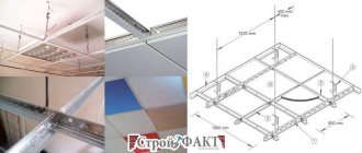
Replacing a lamp in a suspended ceiling
When planning to change LED lamps, you should take into account that some of the lamps and lamps in them are the same. In this case, you will have to change the lamp itself. The procedure is as follows.
Firstly, remember that it is not held in the ceiling film itself, but on a special mounting pad.
Use your hands to gently bend the lamp to reveal the two expanding springs that secure it in place.
When disassembling, these springs will need to be held so as not to catch and break the ceiling itself.
- press the springs in and pull down to remove the lamp
- disconnect the power plug and connect a new point in its place
- now bend the springs inward with your fingers and insert them into the ring of the mounting platform
Sometimes it is not very convenient to do this at the same time, so you start the right side first, and then, pressing the left spring, insert the entire lamp.
Please note: the lamp should not hang on the film. The springs must fit exactly into the ring, which is located behind the film.
Using your thumbs, press the body up, finally sinking it into the ceiling. The lamp is installed in its place. Turn on the switch and check the lighting.
Troubleshooting a remote controlled chandelier
Often, repairs to LED chandeliers need to be done due to overheating of the matrix itself. First, unscrew the fasteners and visually inspect the inside of the chandelier. Then they carefully try to move the board in place. Determine whether there is a break in the wires from the control unit, or whether the wire has burnt out due to overvoltage. If it's burnt out, solder it back in place. We check all the details one by one.
Then you will need an original chandelier diagram. Without it, you can only repair chandeliers without remote control. If there is a remote control unit, change the batteries in it with new elements. LED chandeliers with a control panel are common; here you will need an exact diagram of the chandelier controller to identify a breakdown.
The chandelier control unit is usually tightly sealed into a shell, and manufacturers draw circuits on it. These are just diagrams for connecting wires and lighting elements.
There are also blocks with a collapsible body, then the option is simplified. If the unit is not collapsible, use a tester to check the output signal to the lighting elements (LEDs). If there is no voltage supply, the reason may be a breakdown of the signal receiver. We disassemble it, visually check the contacts and tracks on the board, the integrity of the parts. If voltage is supplied to one lighting branch, then there is a breakdown in the control unit, and not in the signal receiver itself.
The burnt part can be unsoldered and ringed, first, all the resistances (see diagram) by placing an OM symbol on the device. Then the capacitance of the capacitors, fortunately there are symbols on them, polarity and type are also important when checking.
Designation on the diagram
If a discrepancy in the nominal value is detected, we resolder it.
The chandelier control unit is responsible for the intensity and burning modes of the LED elements. Violation of one of the circuits (in the lampshade version of the lamp) does not disable the unit; the fuse may have blown.
But still, check the blocks to see if there are melted places on them, yes, replace it with a new one. If the wires are connected incorrectly, only the parts in the power supply will burn. The regulator block is protected from excessive loads. It can be called according to the diagram.
Video:
Instructions for replacing fluorescent tubes with LED tube lamps
How to remove a lamp from a ceiling or wall
Before you begin upgrading the lamp, you must disconnect it from the electrical wiring. To avoid being exposed to dangerous phase voltage, you need to turn off the voltage supply with the switch and check using an indicator that there is no phase on the terminal block, with which such lamps are usually connected to the electrical network. Although the switch should be set to open the phase wire, in practice electricians do not always comply with this. If there is a phase on the terminal block, then you need to find the circuit breaker through which voltage is supplied to the lamps and temporarily turn it off.
The next step is to disconnect the power supply wires from the terminal block and insulate the bare ends with insulating tape.
yellow-green ground wire PL is also connected to the luminaire body
colors. As a rule, it is pressed with a screw to the part of the lamp body that is bare of paint using a screw, as in the photo. This wire also needs to be released by releasing the screw. The PL ground wire does not need to be insulated.
If there is more than one lamp installed in a room or office, you can now turn on the light to continue working in good light and unscrew the screws holding the lamp to the ceiling. If a fluorescent lamp is removed from an Armstrong-type suspended ceiling, then it is enough to press it up and, turning it around, remove it diagonally from the resulting empty square in the ceiling.
Electrical diagram for connecting a linear LED tube lamp
The supply voltage to each of the two sockets when a linear fluorescent lamp is connected to it is carried out by two wires according to the following electrical diagram.
This is due to the fact that in order to ignite mercury vapor at a low voltage in a fluorescent lamp, it is necessary to create clouds of electrons at its two ends using hot filaments.
An LED linear lamp works on a different principle and for it to start glowing, it is enough to apply a 220 V AC supply voltage directly to the opposite pins of the base, as in the electrical diagram above. Therefore, only one wire needs to be connected to each cartridge. Which of the cartridges will be connected to the phase wire and which to the zero wire does not matter.
Removing unnecessary elements from the lamp
The lamp has been removed and you can begin to remodel it. First of all, it is necessary to remove the fluorescent lamps from the lamp. To do this, you need to grab the fluorescent lamp with both hands near the bases and turn it 90° in any direction. After this, the lamp can be easily removed from the sockets. Before removing the lamp from the ceiling, it is useful to mark the working lamps with a marker; it is quite possible that they will serve in other lamps for some time. Removal of lamps must be done carefully so as not to break them, since their bulbs contain mercury vapors hazardous to human health.
Next, the electrical wires are disconnected from the starters (which looks like a cylinder in a block) and the throttle (which looks like a transformer). The throttle and starters with pads are removed; they will no longer be needed.
Old style starter sockets are attached to the fixture fixture using screws or narrow metal strips. Modern starter cartridges are secured using latches. In order to remove such a cartridge without damaging the mount, you need to squeeze the cylinders of the latches with tweezers and they will easily come out of the holes in the lamp body. Otherwise, the cartridge can be removed by prying it with a screwdriver.
In old cartridges, the current-carrying conductors are secured with screws. Modern cartridges use a screwless method of fastening wires. In order to disconnect the wire without damaging the cartridge, you need to rotate the wire clockwise and back 90° while simultaneously pulling it out with a little force. If the cartridge is not needed, then the wires can be cut off with wire cutters. By the way, wires are also disconnected in this way from other installation products with a screwless fastening method, such as switches, sockets and electrical sockets for chandeliers and lamps.
Electric holder for linear lamps G13 fastening and connection
There are three types of sockets for G13 sockets in fluorescent tube lamps. They differ from each other in the way they are attached to the lamp body and in the way the current-carrying wires are connected to the socket.
The marking of the lamp socket or base indicates: G – pin connection system for the lamp, 13 – distance between the pins, expressed in millimeters.
Since for the LED tube to work, it is enough to connect only one wire to each socket, you can do without dismantling the socket by only connecting one wire coming from the socket to the terminal block. One of the wires coming out of the cartridge is usually short, as it was connected to a previously installed starter. This wire can be shortened and insulated. If the lamp is designed to install several lamps, then the wires from all sockets installed side by side are connected to one terminal using a terminal block. The wires coming from the opposite row of cartridges are connected to the remaining free terminal of the terminal block.
When replacing fluorescent lamps in a luminaire with LED lamps, you can use a Vago-type terminal block to make the installation look neat. You won’t have to deal with insulating the wires and the reliability of connecting the cartridges will increase, since both of its contacts will be connected.
In the photo, the cartridges are mounted using two Vago blocks with four positions each. These were at hand. In this case, it was more expedient to use only one Vago block for five installation locations for wires.
If you don’t have Vago terminal blocks at hand, but you want to do the installation when remaking the lamp at a high professional level, then you will need to dismantle the sockets.
The Soviet-style socket shown in the photograph is attached to the lamp body using screws or a narrow strip of thin metal. The wires in them are inserted into holes on the back side and secured with screws, like in a terminal block. Spring-loaded bushings are inserted into the mounting holes of the cartridges installed on one side. This ensures that the lamp is pressed between the sockets and eliminates the influence of deviations in the geometric dimensions of the lamp fittings.
How to connect Soviet-era cartridges together can be seen in the photograph. If there are more than two cartridges in the lamp, then another jumper is thrown from the free terminal of the cartridge. This installation scheme has a drawback: if you remove the lamp from the socket to which the supply voltage is supplied, then all other lamps will go out. This is due to the fact that voltage is transmitted to adjacent sockets through a jumper between the pins made inside the lamp itself.
After clamping the wire with a screw, you must tug on it; the wire may get past the terminal and therefore remain unclamped.
Modern G13 sockets for linear lamps are mounted on luminaire fittings using latches. To dismantle the cartridge, simply squeeze the latches towards each other using tweezers and the cartridge will easily come out of the mounting holes. Metal springs are also installed on one side of the lamp, but they are flat.
When dismantling and installing cartridges, you need to be very careful and not apply more force than necessary, since the plastic fastening latches can easily break off.
The connection of wires to modern G13 sockets for linear lamps is made with a screwless quick-release system. It is enough to remove the insulation from the conductor to a length of about 10 mm and forcefully insert it into one of the required holes, which are located on the lower plane of the cartridge. Clamping contacts in adjacent holes inside are connected to each other and to a contact that transmits the supply voltage to one of the lamp pins.
Therefore, in order to connect all the cartridges to the power wire, you need to connect them together with jumpers, like the wiring diagram shown in the photo. The length of the jumper between the sockets is selected based on the distance at which the sockets are installed from each other in the luminaire body.
After installing the wires, all that remains is to install the sockets in their original places in the lamp and connect the wire coming from them to the power supply terminal block. The same operation is performed with sockets located on the opposite side of the lamp.
The modification of the lamp is completed and all that remains is to fix it in place, connect the supply voltage to the terminal block and insert the LED tube lamps. With leisurely work, upgrading the lamp to allow the replacement of fluorescent linear lamps with LED lamps took no more than an hour.
Cooling radiators
Many models of regulators, drivers and power supplies of LED lamps come with cooling radiators. They have a seat through which a microcircuit or other control element gives off heat. Most lamps have radiators.
The lack of special lubricant and thermal paste is the reason for overheating of the majority (up to 15%) of boards and units. Unscrew and check whether it is applied along the plane of the seat.
Thermal paste is applied in a thin layer over the entire surface of the seat; a large amount will only worsen heat transfer. By screwing an additional thin aluminum plate to the radiator, you can increase heat transfer, while the installation is carried out without blocking the main air flows passing through it.
Nuances of carrying out work depending on the type of lamp and base
When performing work to replace failed lamps, there are several nuances that should be kept in mind.
- There are no differences in replacing burnt-out light bulbs for stretch and suspended ceilings - the scheme is the same.
- It's easier to change the bulbs of a chandelier - there are no cooling radiators. Therefore, the light bulbs are either unscrewed or pulled out by direct movement towards you.
- When replacing halogen lamps, it is necessary to work with cotton gloves or, in extreme cases, use napkins. A special coating is applied to the outer surface of such lighting fixtures, which burns out upon contact with hand grease, damaging the bulb.
- Screw-type bases often become slightly welded to the socket during voltage surges and do not want to be unscrewed. In this case, the flask is covered with tape or a medical plaster, which allows you to apply a little more effort to remove it from the cartridge.
- When replacing lamps, you must carefully monitor the voltage at which they operate. Visually, it is impossible to distinguish a 12V light bulb from the same one at 220V. The inscriptions on the packaging or base will help you figure it out.