What types of photo sensors are there?
Photosensors in various electronic devices, home and industrial automation devices, and various amateur radio designs .
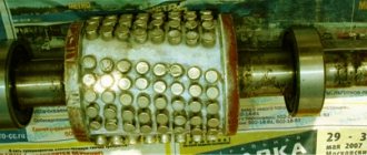
Anyone who has ever disassembled an old computer mouse, as it was called a Komov mouse, with a ball inside, has probably seen wheels with slots spinning in the cracks of the photo sensors. Such photo sensors are called photointerrupters - they interrupt the flow of light. On one side of such a sensor there is a source - an LED, usually infrared (IR), on the other a phototransistor (to be more precise, two phototransistors, in some models a photodiode, to also determine the direction of rotation). When the wheel with slots rotates, electrical impulses are generated at the output of the photosensor, which is information about the angular position of this very wheel. Such devices are called encoders. Moreover, the encoder can simply be a contact one, remember the wheel on a modern mouse!
Photointerrupters are used not only in mice, but also in other devices, for example, speed sensors of any mechanism. In this case, a single photosensor is used, because the direction of rotation does not need to be determined.
If for some reason, most often for repair, one gets into other electronic devices, then photo sensors can be found in printers, scanners and copiers, in CD drives, in DVD players, video cassette recorders, video cameras and other equipment.
So what types of photo sensors are there, and what are they? Let’s just see, without delving into the physics of semiconductors, without understanding the formulas and without uttering incomprehensible words (recombination, resorption of minority carriers), what is called “on the fingers”, how these photosensors work.
Figure 1. Photointerrupter
Photoresistor
Everything is clear with him. Just like a regular constant resistor has an ohmic resistance, the direction of connection in the circuit does not matter. Only, unlike a constant resistor, the resistance changes under the influence of light: when illuminated, it decreases several times. The number of these “times” depends on the model of the photoresistor, primarily on its dark resistance.
Structurally, photoresistors are a metal case with a glass window, through which a grayish plate with a zigzag track is visible. Later models were made in a plastic case with a transparent top.
The speed of photoresistors is low, so they can only operate at very low frequencies. Therefore, they are almost never used in new developments. But it happens that in the process of repairing old equipment you will have to meet with them.
To check the health of the photoresistor, just check its resistance using a multimeter. In the absence of lighting, the resistance should be high, for example, the photoresistor SF3-1 has a dark resistance of 30 MOhm according to reference data. If you illuminate it, the resistance drops to several kOhms. The appearance of the photoresistor is shown in Figure 2.
Figure 2. Photoresistor SF3-1
Photodiodes
Very similar to a regular rectifier diode, if not for their ability to react to light. If you test it with a tester, preferably an outdated pointer tester, then in the absence of lighting the results will be the same as in the case of measuring a conventional diode: in the forward direction the device will show a small resistance, and in the reverse direction the needle of the device will hardly budge.
They say that the diode is turned on in the opposite direction (this point should be remembered), so no current flows through it. But, if in such a connection the photodiode is illuminated with a light bulb, the arrow will sharply rush to the zero mark. This mode of operation of the photodiode is called photodiode.
The photodiode also has a photovoltaic mode of operation: when light hits it, like a solar battery, it produces a weak voltage, which, if amplified, can be used as a useful signal. But, more often the photodiode is used in photodiode mode.
Photodiodes of the old design look like a metal cylinder with two terminals. On the other side there is a glass lens. Modern photodiodes have a housing simply made of transparent plastic, exactly the same as LEDs.
Rice. 2. Photodiodes
Phototransistors
In appearance they are simply indistinguishable from LEDs, the same case is made of transparent plastic or a cylinder with a piece of glass at the end, and there are two outputs from it - a collector and an emitter. The phototransistor does not seem to need a base output, because the input signal for it is the luminous flux.
Although, some phototransistors still have a base output, which allows, in addition to light, to control the transistor electrically. This can be found in some transistor optocouplers, for example AOT128 and imported 4N35 - essentially functional analogues. A resistor is connected between the base and emitter of the phototransistor to slightly cover the phototransistor, as shown in Figure 4.
Figure 3. Phototransistor
Our optocoupler usually has 10-100KOhm, but the imported “analogue” has about 1MOhm. If you put even 100KOhm, it will not work, the transistor is simply tightly closed.
How to test a phototransistor
It is quite easy to check a phototransistor with a tester, even if it does not have a base output. When the ohmmeter is connected in any polarity, the resistance of the collector-emitter section is quite large, since the transistor is closed. When light of sufficient intensity and spectrum hits the lens, the ohmmeter will show a small resistance - the transistor has opened, if, of course, it was possible to guess the polarity of the tester connection. In fact, this behavior resembles a regular transistor, only this one opens with an electrical signal, and this one with a light flux. In addition to the intensity of the light flux, its spectral composition plays a significant role. For details on testing transistors, see here.
Light spectrum
Typically, photo sensors are tuned to a specific wavelength of light. If this is infrared radiation, then such a sensor responds poorly to blue and green LEDs, but quite well to red, incandescent lamps and, of course, to infrared. It also does not perceive light from fluorescent lamps well. Therefore, the cause of poor performance of the photosensor may simply be an inappropriate spectrum of the light source.
It was written above how to ring a photodiode and phototransistor. Here you should pay attention to such a seemingly trifle as the type of measuring device. In a modern digital multimeter in semiconductor testing mode, the plus is located in the same place as when measuring DC voltage, i.e. on the red wire.
The result of the measurement will be the voltage drop in millivolts across the pn junction in the forward direction. As a rule, these are numbers in the range of 500 - 600, which depends not only on the type of semiconductor device, but also on the temperature. As the temperature increases, this figure decreases by 2 for every degree Celsius, which is due to the temperature coefficient of resistance of the TCS.
Determination using a multimeter
Before measuring the resistor, it is necessary to visually determine its integrity: inspect it for burnt outer coating - paint or varnish, and also check the inscriptions on the body, if they are visible. You can determine the denomination using tables of rows or color codes , after which you can measure the resistance using a multimeter.
For testing, you can use a simple measuring device, for example, DT-830B. First of all, you need to set the measurement switch to the minimum resistance test mode - 200 Ohms, and then connect the probes to each other. The device indicator with the probes connected should show the minimum value R, which tends to zero, for example, 0.03 Ohm. After the so-called calibration, you can begin measurements.
Testing the LED with a multimeter
Sequence of actions for testing an LED with a multimeter:
- Prepare the light-emitting diode. In order to ring an LED that is in operation, it is first removed (unsoldered) from the installation site.
- Prepare your multimeter. The switch scale sets the “diode check” or “continuity” position, which is indicated by the diode circuit.
Schematic designation of a diode on a multimeter
The multimeter probes are connected to the contacts of the LED element. Because
the latter is characterized by “unidirectionality” of the electric current; it is important to observe polarity: the red probe is connected to the “plus” anode, the black one to the “minus” cathode.
When connected correctly, the light crystal will produce a slight glow that is difficult to notice in daylight. Therefore, it is recommended to darken the room.
The slight glow is due to the low value of the test current. For the same reason, the LED will not lose its performance characteristics if the polarity is incorrect.
- Check the multimeter readings. When connected correctly, the voltage drop of the working crystal exceeds unity. If the connection is incorrect and/or inoperative, the value will not change and will be one.
Testing the LED with a multimeter, taking into account polarity
You can check a separate LED on the legs with a tester using the transistor sockets of the PNP block. The legs are inserted into the sockets according to the polarity: the “plus” of the anode into the emitter E, the “minus” of the cathode into the collector C. A working LED diode will have a slight glow.
Checking the LED on the legs using the PNP block of the multimeter
Checking the resistance on the board
Elements with an ohmic resistance of up to 200 Ohms must be tested in this measurement range. If the instrument readings indicate infinity, it is necessary to increase the measured range with a switch from 200 Ohms to 2000 Ohms (2 kOhms) and higher, depending on the rating being tested. Before checking a resistor with a multimeter without desoldering it, you need to:
- turn off the power source;
- unsolder one pin R, since due to the mixed connection of elements in the circuit there may be differences between the nominal value of the element and the readings of its actual value in the overall circuit during measurement;
- make a measurement.
Only low-resistance resistances can be ringed on the board, ranging from one ohm to tens of ohms. Starting from 100 Ohms and above, it becomes difficult to measure them, since the circuit may use radioelements that have a lower resistance than the resistor itself.
In addition to fixed resistors, there are the following types of elements:
- variable (rheostat);
- tuning;
- thermistor or negative temperature coefficient thermistor;
- posistor with positive temperature coefficient;
- The varistor changes its values depending on the voltage applied to it;
- the photoresistor changes its values depending on the light flux directed at it.
Checking the resistor with a multimeter to measure the performance of variables and trimming elements is carried out by connecting to the middle terminal of one of the probes, to any of the extreme terminals of the second probe. It is necessary to adjust the slider of the measured element in one direction all the way and back, and the reading of the device should change from the minimum to the nominal or actual resistance of the resistor. Similarly, you need to measure with the second extreme terminal of the potentiometer.
To check a posistor with a multimeter, you need to connect the measuring device to the terminals and bring it closer to the heat source. The resistance should increase depending on the temperature applied to it. Those who work with electronics know how to test a thermistor with a multimeter. Before this, you need to take into account that when it is exposed to the temperature of a heated soldering iron, its thermal resistance should decrease. Before checking the thermistor and posistor on the board, you need to unsolder one of the pins and then take a measurement.
Thermistors can operate at both high and low temperatures. PTC resistors and thermistors are used where it is necessary to control temperature, for example in electronic thermometers, temperature sensors and other devices.
Thermistors in the circuit are used as temperature stabilizers of cascades in power amplifiers or power supplies to protect against overheating. The thermistor can look like a bead with two wires, or it can be shaped like a plate with two leads.
Advantages and disadvantages
These elements have a significant drawback - the cutoff frequency. It sets the maximum frequency of the sinusoidal signal that regulates the luminous flux.
As a result, the sensitivity of the device is significantly reduced. Accordingly, the performance of devices also decreases, where it takes about ten microseconds to respond - 10^(−5) s.
Some inertia of sensors based on photoresistors also appears. There is a delay in the signal, and this negatively affects the performance of the devices.
But there are also positive aspects.
At a low sensitivity threshold, the photoresistor is inexpensive and its connection is justified by high reliability. Often, it is even useful that the photocell is triggered not instantly, but incrementally, gradually. This feature makes it possible to use these parts in analog-type devices - various sensors and light meters.
How to determine the health of SMD resistors
SMD resistors are surface-mount components, the main difference of which is the absence of holes in the board. The components are installed on the current-carrying contacts of the printed circuit board. The advantage of SMD components is their small dimensions , which makes it possible to reduce the weight and size of printed circuit boards.
Testing SMD resistors with a multimeter becomes more difficult due to the small size of the components and their labels. The resistance value on SMD components is indicated as a code in special tables, for example, the designation 100 or 10R0 corresponds to 10 Ohms, 102 indicates 1 kOhm. Four-digit designations may occur, for example 7920, where 792 is the value and 0 is the multiplier, which corresponds to 792 ohms.
Designation on diagrams
A photoresistor on a circuit diagram is designated almost the same as a standard resistor. But there is a slight difference. This is still the same rectangle, but in a circle, outside of which there is an image of two arrows at an angle of 45°. These arrows symbolically show the radiation flux incident on the element.
This designation was adopted by the international electrotechnical commission IEC (International Electrotechnical Commission).
In foreign sources you can see another symbol. The photocell is conventionally shown as a broken line. This is an outdated symbol, but it can also be found on diagrams quite often.
Photoresistor and Arduino
Photoresistors give you the ability to sense the intensity of light.
They are small, inexpensive, require little energy, are easy to use, and are practically not subject to wear.
It is because of this that they are often used in toys, gadgets and gadgets. Of course, DIY projects based on Arduino could not ignore these wonderful sensors.
Photoresistors are essentially resistors that change their resistance (measured in ohms) depending on how much light hits their sensing elements. As mentioned above, they are very cheap, come in different sizes and specifications, but most are not very accurate. Each photoresistor behaves slightly differently from the other, even if they are from the same batch from the manufacturer. Differences in readings can reach 50% or even more! So you shouldn’t count on precision measurements. They are mainly used to determine the general level of illumination in specific, “local” rather than “absolute” conditions.
Photoresistors are an excellent choice for solving problems like “is the environment dark or light”, “is there something in front of the sensor (that limits the flow of light)”, “which area has the maximum level of illumination”.
What is it and where is it used
A phototransistor is a fiber optic semiconductor device that is used to control electric current using a specific optical radiation. These devices are based on a conventional transistor. Their modern counterparts are photodiodes, but phototransistors are better suited for many modern radios and electronic devices. According to the principle of operation, they also resemble photoresistors.
Photo – phototransistor
Unlike photodiodes, these semiconductors have higher sensitivity.
Where is phototransistor used?:
- Security systems (mainly using IR phototransistors);
- Coders;
- Computer logic control systems;
- Photo relay;
- Automatic lighting control (infrared photo semiconductor is also used here);
- Level sensors and data counting systems.
It should be noted that due to the Volt range, photodiodes are much more often used in such systems, but phototransistors have several significant advantages :
- Can produce more current than photodiodes;
- These radio components are comparatively very cheap;
- Can provide instantaneous high current output;
- The main advantage of the devices is that they can provide high voltage, which, for example, photoresistors cannot do.
At the same time, this LED analogue has significant disadvantages , which makes the phototransistor a rather highly specialized part:
- Many semiconductor devices are made of silicone and cannot handle voltages greater than 1000 volts.
- These radio components are very sensitive to voltage drops in the local electrical network. If the diode does not burn out from a voltage surge, then the transistor will most likely fail the test;
- The phototransistor is not suitable for use in lamps because it does not allow directional charged particles to move quickly.
Average technical characteristics of photoresistors
The specifications below are for photoresistors from the Adafruit store. These photoresistors have similar characteristics to the PDV-P8001. Almost all photoresistors have different technical characteristics, although they work very similarly. If the seller gives you a link to the datasheet of your photoresistor, check them out, and not what is stated below.
- Size: Round, 5mm (0.2″) in diameter (other photoresistors can be up to 12mm/0.4″ in diameter!).
- Price: About $1.00 at Adafruit.
- Resistance range: from 200 kOhm (dark) to 10 kOhm (light).
- Sensitivity Range: Sensing elements detect wavelengths ranging from 400 nm (purple) to 600 nm (orange).
- Power: any with voltage up to 100 V, use a current of about 1 mA on average (depending on the supply voltage).
Problems when using multiple sensors
If, when adding additional sensors, it turns out that the temperature is inconsistant, this means that the sensors overlap each other when reading information from different analog pins. This can be corrected by adding two readings with delays and displaying the first one.
Continuity of individual LEDs
This type of test is one of the simplest and is done using a multimeter. A standard LED has two long contacts - an anode and a cathode. The cathode leg is slightly longer, and when viewed against the light, its electrode inside the housing is larger. In order to ring the LED, you must perform the following steps:
- move the switch to the Hfe position (this is the transistor test mode);
- find the connector on the panel marked PNP and NPN;
- The anode is inserted into slot C of the PNP zone, and the cathode is inserted into slot E of the NPN zone.
These pins are the positive and negative electrodes and cause the LED to glow. If this does not happen, then either the polarity is reversed (the diode leads must be swapped), or the element is faulty. Before checking an LED with a multimeter, it is recommended to determine where its anode and cathode are.
Since multimeters have different designs and characteristics, there are several types of sockets for testing transistors.
Despite the differences, they all have the required slots.
Light level measurement
As we have already said, the resistance of the photoresistor changes depending on the lighting level. When it is dark, the resistance of the resistor increases to 10 megohms. As the light level increases, the resistance decreases. The graph below shows the approximate sensor resistance under different lighting conditions. Do not forget that the characteristics of each individual photoresistor will be slightly different, these characteristics reflect only the general trend.
Please note that the characteristic is not linear, but has a logarithmic character.
Photoresistors do not perceive the entire range of light waves. In most versions they are sensitive to light waves in the range between 700 nm (red) and 500 nm (green).
That is, an indication of the light wavelength range that corresponds to blue will not be as effective as an indication of the green/yellow range!
What is the unit of measurement "lux"?
Most datasheets use lux (lx) to indicate resistance at a certain light level. But what is this - lk? This is not a method we use to describe brightness, so it is tied directly to the sensor. Below is a correspondence table that was taken from Wikipedia.
Kinds
In general, all photo sensors are divided into two main groups:
- Parts with an internal photoelectric effect.
- Details with external photo effect.
They are distinguished from each other by production technology, or, to be more precise, by the very composition of the photoresist layer.
If in the first case the purest chemical components are used during production, without foreign impurities. Thus, the characteristics of the sensor change; the photoresistor practically does not react to visible light, but works well in the infrared range.
The latter, on the contrary, contain impurities in the semiconductor substance. Due to this, the sensitivity spectrum in the visible light zone expands and even covers the infrared range (heat rays).
Although the operating principle and how to connect these two types are no different - the internal resistance decreases with increasing intensity of the light flux incident on them.
Actually, this property helps when installing boards with photosensors. The question of how to check a photoresistor is solved by checking its resistance with a multimeter. The working element should have greater resistance in the absence of lighting. If light is applied to its sensitive element, the resistance will instantly drop to several kOhms.
Checking the photoresistor
The simplest method of testing your photoresistor is to connect a multimeter in resistance measurement mode to the two contacts of the sensor and track the change in output resistance when you cover the sensor with your palm, turn off the light in the room, etc. Since the resistance varies over large ranges, the automatic mode works well. If you don't have an automatic mode or it doesn't work correctly, try the 1 MΩ and 1 kΩ range.
Preparing the multimeter for use
How to check the UPS for functionality
First of all, let's take our multimeter out of the package and examine it carefully. There should be no damage to the case, and the battery compartment should close tightly. We check the quality and integrity of the probes and the wires going to them. If there is no insulation, use electrical tape. Heat-shrink tubing will also do the job well. If there are chips on the probes, we also wrap them.
We set the mode switch to work with ohms, opposite the 200 Ohm division. We connect the black cable to the Com socket. We connect the red cable to the socket where there are symbols of the quantities that we are going to measure.
The device should display the number “1” on its screen. If it's missing or something else is displayed, it's time to repair it. We cross the probes with each other. The one changes to a zero. If this is exactly what happens, then work is proceeding as usual. If the numbers are flickering on the screen, they are pale, you need to try changing the batteries. If the attempt fails, the device must be repaired. To start testing the lamp, set the break search mode on the toggle switch. This mode is indicated by a diode icon.
Photoresistor connection
Since photoresistors are essentially resistance, they have no polarity. This means that you can connect their legs 'any way you like' and they will work!
Photoresistors are really unpretentious. You can solder them, install them on a breadboard, or use clips for connection. The only thing you should do is bend the 'legs' too often, as they can easily break off.
What multimeter will we use?
The multifunction multitester Victor VC9805 was used as a multimeter, although any digital tester, like the familiar DT-83x or MAS-83x, is suitable for measurements.
Such multimeters can be bought not only at radio markets, radio parts stores, but also at auto parts stores. A suitable multimeter can be bought on the Internet, for example, on Aliexpress. First, we will check the domestically produced silicon bipolar transistor KT503. It has an npn structure. Here is its pinout.
For those who don’t know what this incomprehensible word pinout means, I’ll explain. Pinout is the location of the functional pins on the body of the radio element.
For a transistor, the functional terminals will respectively be the collector (K or English - C), emitter (E or English.
- E), base (B or English - C).
First, we connect the red ( ) probe to the base of the KT503 transistor, and the black (-) probe to the collector terminal. This is how we check the operation of the pn junction in direct connection (that is, when the junction conducts current). The breakdown voltage value appears on the display. In this case it is equal to 687 millivolts (687 mV).
Next, without disconnecting the red probe from the base terminal, we connect the black (“negative”) probe to the emitter terminal of the transistor.
As we can see, the pn junction between the base and emitter also conducts current. The display again shows the breakdown voltage value equal to 691 mV. Thus, we checked the B-K and B-E transitions when connected directly.
To make sure that the pn junctions of the KT503 transistor are working properly, let’s check them in the so-called reverse connection. In this mode, the pn junction does not conduct current and the display should show nothing other than "1". If the display shows “1”, this means that the junction resistance is high and it does not allow current to pass through.
To check the pn junctions B-K and B-E in reverse connection, we change the polarity of connecting the probes to the terminals of the KT503 transistor. We connect the negative (“black”) probe to the base, and the positive (“red”) probe first connects to the collector terminal...
...And then, without disconnecting the negative probe from the base output, to the emitter.
As we can see from the photographs, in both cases the display showed a “1”, which, as already mentioned, indicates that the pn junction does not pass current. So we checked the transitions B-K and B-E in reverse connection.
If you carefully followed the presentation, you will have noticed that we tested the transistor according to the previously outlined method. As you can see, the KT503 transistor turned out to be working.
If any of the transitions (B-K or B-E) are broken, then when you check them on the multimeter display, you will find that in both directions, both in direct connection and in reverse, they show a non-breakdown voltage of the pn junction, and resistance. This resistance is either equal to zero “0” (the buzzer will squeak) or will be very small.
If there is a break, the pn junction does not pass current either in the forward or reverse direction - the display will show “1” in both cases. With such a defect, the pn junction turns into an insulator.
Testing bipolar transistors of the pnp structure is carried out in a similar way. But in this case it is necessary to change the polarity of connecting the measuring probes to the terminals of the transistor. Let us recall the drawing of a conventional image of a pnp transistor in the form of two diodes. If you forgot, then look again and you will see that the cathodes of the diodes are connected together.
As a sample for our experiments, we will take the domestic silicon transistor KT3107 of pnp structure. Here is its pinout.
In the pictures, checking the transistor will look like this. We check the B-K transition when connected directly.
As you can see, the transition is correct. The multimeter showed the breakdown voltage of the junction - 722 mV.
We do the same for the B-E transition.
As you can see, it is also working properly. The display shows 724 mV.
- Now let’s check the serviceability of the transitions in the opposite direction - for the presence of a “breakdown” of the transition.
- Transition B-K when switched back on...
- Transition B-E during reverse switching.
In both cases, the device display shows “1”. The transistor is OK.
Let's summarize and describe a short algorithm for checking a transistor with a digital multimeter:
- Determination of the transistor pinout and its structure;
- Checking transitions B-K and B-E in direct connection using the diode test function;
- Checking the B-K and B-E transitions in reverse connection (for the presence of a “breakdown”) using the diode test function;
When checking, it is necessary to remember that in addition to conventional bipolar transistors, there are various modifications of these semiconductor components. These include composite transistors (Darlington transistors), “digital” transistors, line transistors (the so-called “line transistors”), etc.
They all have their own characteristics, such as built-in protective diodes and resistors. The presence of these elements in the structure of the transistor sometimes complicates their testing using this technique.
Therefore, before checking a transistor unknown to you, it is advisable to read the documentation for it (datasheet).
Home » Radio electronics for beginners » Current page
Using photoresistors
Analog voltage reading method
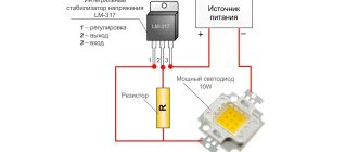
The simplest use case is to connect one leg to the power source, the other to ground through a pull-down resistor. After this, the point between the fixed resistor and the variable resistor - the photoresistor - is connected to the analog input of the microcontroller. The figure below shows the connection diagram to Arduino.
In this example, a 5V power supply is connected, but remember that you can just as easily use a 3.3V supply. In this case, the analog voltage values will be in the range from 0 to 5V, that is, approximately equal to the supply voltage.
It works as follows: as the resistance of the photoresistor decreases, the total resistance of the photoresistor and the step-down resistor decreases from 600 kOhm to 10 kOhm. This means that the current passing through both resistors increases, which causes the voltage across the 10k resistor to increase. That's all!
This table provides approximate analog voltage values based on light level/resistance when connecting a 5V supply and a 10k ohm pull-down resistor.
If you want to use the sensor in a brightly lit area and use a 10k ohm resistor, it will quickly blow away. That is, it will almost instantly reach the permissible voltage level of 5 V and will not be able to distinguish between more intense lighting. In this case, you should replace the 10k ohm resistor with a 1k ohm resistor. With this circuit, the resistor will not be able to detect the level of darkness, but it is better to determine the shades of a high level of illumination. In general, you should play around with this depending on your conditions!
Additionally, you will also be able to use the "Axel Benz" formula to basicly measure the minimum and maximum resistance value using a multimeter and then find the resistor value using: Pull Resistor = Square Root(Rmin * Rmax), which will give you a much better result result in the form:
The table above shows approximate analog voltages when using a 5V sensor with a 1K pull-down resistor.
Don't forget that our method does not give us a linear dependence of voltage on illumination! In addition, each sensor has different characteristics. As the light level increases, the analog voltage will rise and the resistance will fall:
Vo = Vcc(R/(R+Photocell))
That is, the voltage is inversely proportional to the resistance of the photoresistor, which, in turn, is inversely proportional to the lighting level.
digital electronics computing embedded systems
How to check a photocell
Photocells are detectors that depend on light to operate. When they are far from light, they have high resistance. When placed near light, their resistance drops. When placed inside circuits, they allow a certain amount of current to flow based on the consumed amount of light that illuminates them, and are therefore called photoresistors. They are also called light dependent resistors or LDRs.
Photovoltaic cells are made from semiconductors, most often cadmium sulfide. Those made from lead sulfide are used to detect infrared radiation.
To test the photocell, use a digital multimeter. Turn on the multimeter and set it to measure resistance. Resistance is usually indicated by the Greek letter omega. If the multimeter does not auto-adjust, turn the knob to a very high level, such as megaohm.
Place the red multimeter probe on one photocell terminal and the black probe on the other. The direction doesn't matter. You may need to use alligator clips to make sure the probes don't slip off the photocell wires.
Protect the photocell so that light does not reach it. Do this by placing your hand on it or, for example, covering it. Record the resistance value. It should be very high. You may need to change the resistance measurement setting up or down to get a reading.
Open the photocell to allow light to shine on it. Adjust the knob on your multimeter to lower its resistance measurement setting. After a few seconds the resistance should read hundreds of ohms.
Repeat the experiment by placing the solar cell near different light sources, including testing it in sunlight, moonlight, or in a partially darkened room. Record the resistance each time. Photocells can take anywhere from a few seconds to a few minutes to adjust when they are removed from a light source and then placed in the dark. As before, you may need to change the resistance measurement settings to get the correct readings.
Source
Simple code for analog light level measurements
The sketch does not perform any calculations, only displaying values that are interpreted as lighting levels. For many projects this is quite enough.
/* A simple test sketch for a photoresistor.
Connect one leg of the photoresistor to 5 V, the other to the Analog 0 pin.
After that, connect the pin of the 10 kOhm resistor to ground, and the second one to the analog pin Analog 0 */
int photocellPin = 0; // sensor and 10 kOhm pull-down resistor connected to a0
int photocellReading; // data read from the analog pin
// Transfer information for debugging to the serial monitor
Serial.print(photocellReading); // analog values
> else if (photocellReading
> else if (photocellReading
> else if (photocellReading
Serial.println(" - Very bright");
This test was carried out in a room during the day. I covered the sensor with my hand, and then with a piece of cloth.
How to test a transistor with a multimeter: instructions, video
In the world of electronics, there are a large number of different devices and parts. They number in the millions and are constantly increasing with the invention of more and more new devices.
Despite the large number of electronic elements, every specialist in this field knows about transistors. This is a radio-electronic device operating at special frequencies, which has 3 outputs. Its job is to reduce current resistance.
READ MORE: How butt welding of polyethylene pipes is performed, instructions for carrying out the work
- As you might have guessed, today we will talk about how to test a transistor with a multimeter.
- Before you start working with a multimeter, you need to know how to use it, know what model you are using, and also be able to connect it to the network.
- You can find out what model you are using by looking at its markings.
- Usually the marking is on the box of the device and there is complete information about it, namely:
- Transistor model.
- Manufacturer country.
- Issuing company.
- Product warranty.
- If for some reason you do not have a transistor box, you can fix this by searching for a similar photo on the Internet, where there will be a detailed description of the device.
Next we will talk about instructions on how to test a transistor:
- Attach the large red probe (CEM) - this will be considered a minus, and attach the black one to (MA) - this will be a plus.
- Next, you need to turn on the device and redirect it to the dialing mode or you can switch it to the resistance mode at your discretion.
- After which you will see the energy resistance value on the screen. Normally, it ranges from 0.3 to 0.7 Ohm.
- To display the minimum resistance, you need to indicate the power of your transition, and after all that has been done, your device is fully configured and ready for its active and long-term use.
- Soldering any part from an electrical appliance is a very responsible matter, in which the slightest mistake can completely damage any electrical appliance.
- So how can you test a transistor without desoldering it from the circuit?
- First you need to ensure its integrity.
- Then check its generation.
- Next, you should pay attention to L2, which is located near the opening of the red probes.
- The glow of lamp L2 indicates its performance.
If lamp L2 does not light, then this is a sure sign that the device is broken.
In this case, it is not recommended to repair it yourself, since there is a high probability that you will damage other parts during the repair.
- We advise you to contact a competent specialist with this problem who can repair the transistor.
Now we move on to how to test the transistor on the board? It should be noted that this is one of the most popular questions on this topic.
It must first be connected to the positive base using a powerful source. If you do everything correctly, your light should light up.
- To carry out a similar test, you need to carefully apply a minus signal, as a result of which the light bulb should stop glowing.
Carrying out such simple manipulations with the device should certify that the part is working properly. If you do not get such results, then this indicates a breakdown of the transistor.
The IGBT transistor was created in Lithuania, and therefore it will be somewhat different from domestic devices. To check it, you need to make a cascade connection in a bipolar structure and then look at the indicators.
Next, switch the device to semiconductor mode. If all manipulations are done correctly, this is an indicator of the serviceability of the multimeter.
Conclusion
Thank you for using our article. We tried to correctly express our thoughts and answer all your questions.
When working with electrical appliances, be careful and then working with them will bring incredible enthusiasm and pleasure. Good luck!
Semiconductor elements are used in almost all electronic circuits. Those who call them the most important and most common radio components are absolutely right.
But any components do not last forever; overvoltage and current, temperature violations and other factors can damage them.
We will tell you (without overloading with theory) how to check the performance of various types of transistors (npn, pnp, polar and composite) using a tester or multimeter.
Where to begin?
Before checking any element with a multimeter for serviceability, be it a transistor, thyristor, capacitor or resistor, it is necessary to determine its type and characteristics. This can be done by marking.
Once you know it, it won’t be difficult to find a technical description (datasheet) on thematic sites. With its help, we will find out the type, pinout, main characteristics and other useful information, including replacement analogues.
For example, the scanning on the TV stopped working. Suspicion is raised by the line transistor marked D2499 (by the way, a fairly common case). Having found a specification on the Internet (a fragment of it is shown in Figure 2), we receive all the information necessary for testing.
Figure 2. Specification fragment for 2SD2499
There is a high probability that the datasheet found will be in English, no problem, the technical text is easy to understand even without knowledge of the language.
Having determined the type and pinout, we solder the part and begin testing. Below are the instructions with which we will test the most common semiconductor elements.
Reading values from a photoresistor without using analog pins
Reading values from a photoresistor without using analog pins
Since photoresistors are essentially just resistors, they can be used even if your microcontroller has no analog pins (or if all the analog pins are occupied). This method is based on the basic properties of resistors and capacitors. If you take a capacitor that can transfer potential and connect it to a power source (eg 5V) through a resistor, the change in voltage will occur gradually. The higher the resistance of the resistor, the slower the voltage will change.
Below is a piece of the oscillogram that characterizes what exactly is happening with the digital pin (yellow). The blue line shows when the Arduino sketch itself begins to work and when it finishes its work (a section lasting about 1.2 ms).
If we draw simple analogies, the capacitor acts as a basket, and the resistor acts as a tube. Filling the basket with a thin tube will take a long time. Depending on the thickness of the tube, the filling speed of the basket will vary.
In our case, the 'basket' is a ceramic resistor with a capacity of 0.1 µF. You can experiment with the capacitance of the capacitor. And this indicator will directly affect the time. If you want to measure the light level, use a 1 µF capacitor. If you work in low light conditions, you can use a 0.01 uF capacitor.
/* a simple sketch to check the functionality of a photoresistor.
Connect one leg of the photoresistor to the power supply, the other to pin 2.
After this, connect one leg of the 0.1 uF capacitor to pin 2, and the other to ground */
int photocellPin = 2; // photoresistor connected to pin 2
int photocellReading; // digital values
int ledPin = 13; // you can use the built-in LED
// send information for debugging to be displayed in the serial monitor window
pinMode(ledPin, OUTPUT); // use LED as output signal
// read readings from the sensor using RCtime technology
if (photocellReading == 30000)
// if the reading reaches 30000, it means we have reached the limit value
Serial.println(photocellReading); // stream of read analog data
// the brighter, the more often the LED flashes!
// use digital pin to measure resistance
//we do this by applying current to the capacitor and
//calculating how long it will take to reach Vcc/2 (for most Arduinos this value is 2.5V)
int RCtime(int RCpin)
int reading = 0; // start from 0
// initialize the pin as output and assign it the value LOW (ground)
// Now set the pin as input and.
reading++; // increment for counting time
if (reading == 30000)
// if we get to this level, the resistance is so great
// that most likely nothing is connected!
break; // go outside the loop
How to choose a photo relay
Please note that each device has a designated area of applicability. For our case, this is throughput. A photo relay is not capable of passing an infinitely large current; the power element will melt. It is important to understand that sometimes you can’t get by with just a key. The original solution is to replace discharge and conventional lamps with LED or energy-saving ones. Such devices consume an order of magnitude less energy, which means it is permissible to supply 10 times more quantity.
The service life of LED lamps can reach 30,000 hours. The Chip&Dip store provides a two-year warranty on the goods sold of the specified type. Filamentous LEDs are made to imitate conventional incandescent lamps and can last for years. At the same time, they are not afraid of shaking, are economical and relatively cheap. The neighbors will not understand that a change has taken place.
When creating a connection diagram for a photo relay for street lighting, you need to think about power and power issues. Agree, it is inconvenient to install a number of control keys. They spoil the appearance of the exterior and carry no meaning, except to highlight several circuits designed to turn on and off at different times. Any owner of a private home knows the facts:
- During the design development period, the house is equipped with an electrical project. You can’t take and change something without a lot of coordination work. Therefore, the less the photo relay costs and affects the circuit, the better. Then changing incandescent or discharge light bulbs to LED or energy-saving ones seems appropriate. The main thing is that the current passed through will decrease, you will be able to save on relays, and also get by with only one for the entire estate.
- An important part is the energy quota. According to the laws of the Russian Federation, the owner has the right to a certain share of energy. This is called a quota. If you don’t choose your share - which is already taken into account in the electrification project - then you will have to (!) pay for what is due. It is better to know your own quota in advance. And you cannot exceed it for fear of a progressive fine. Therefore, it is profitable to take exactly as much as the law gives. Saving energy through external lighting will allow a little more devices to be placed inside the building.
Checking the resistor with a multimeter
A black probe is inserted into the COM connector, and a red one into the VΩ connector. VΩ is a measurement of voltage and resistance.
One denotes two situations. If the resistor has a resistance higher than the selected limit, the multimeter will show an off-scale value. A unit also means that the device does not see the radio component or there is poor contact between the probes and the part.
A dot on the screen shows the measurement limit. Here the limit selected is 20 kOhm.
The multimeter shows 2.7 kOhm. When taking measurements, you must not touch two metal bases of the probes at the same time. Your body may shunt the part being measured and the parting reading will be false.
The same thing applies to resistors whose resistance ratings are higher than that of the device being measured. You can also check it using a diode test. If the resistor is working properly, the diode continuity test will not squeak, it will show a voltage drop. But there is a problem here too.
Testing a mercury arc lamp
A lamp with an arc mercury phosphor lamp (MAFL) can usually be found on the street or in a factory workshop. To determine the performance, the choke is called - a device that limits the current that supplies the DRL.
If the circuit was broken, then the resistance will be unlimitedly large, as the device will show. If there is a loss of insulation leading to a short circuit, the value increases slightly. If there is a short circuit in the inductor winding, the resistance does not change.
If no problems were identified when checking the choke tester, then the arc lamp may not function due to malfunctions in the power supply system, for example, due to oxidation of the contacts. The principle of operation of the lamp is very simple, so malfunctions directly in the DRL lamp are rare.
How to replace a faulty one
Consider the chain in which the part needs to be replaced. If the resistor is SMD, then only the same +-5% of the nominal value will do. If this is a DIP resistor that is located in the power supply, then you can get by with a larger error. The problem is that some circuits can be designed for a large error, but there are no circuits for precision instruments. SMD components have lower capacitance and inductance than DIP. And at the same time, SMDs are not designed for high power.
You can also combine different resistors into one needed one for temporary repairs. For example, a 2 W resistor with a resistance of 10 kOhm turns black and overheats. What can replace it? You can connect two 20 kOhm 2 W resistors in parallel, and you get an equivalent power of 4 W and a resistance of 10 kOhm. Or you can connect two 5 kOhm 2 W in series. And you get a 10 kOhm 4 W resistor.
Design and principle of operation of a photo relay
After reading the subsection, a person who understands circuits will no longer need to explain how the photo relay FR 601 is connected. The main structural parts of any street photo relay designed to control the level of illumination around the house:
- The power supply is located right at the entrance. This part gives the photo relay the necessary weight. The sensor is the size of a five-kopeck coin. Inside the photo relay power supply is not pulsed, but a simple one. Under the casing of the photo relay there is a large transformer hidden. It digests voltage from a 220 V network into a form suitable for powering a photodiode. The entire device is a power supply for a small piece of semiconductor the size of a fingernail. Now it’s clear why there is a neutral wire in the photo relay: to power the primary winding of the transformer. This is not the only reason. The photo relay transformer is, of course, step-down. The voltage required to power the photodiode is removed from the secondary winding.
The entire diagram is presented. Let us add that “ground” is sometimes needed for the correct operation of power elements (to set the operating point of a nonlinear element).
Basic ways to check a transistor
The transistor is a very important element in most radio circuits. Those who decide to engage in radio modeling must first of all know how to test them and what devices to use.
A bipolar transistor has 2 PN junctions. The outputs from it are called emitter, collector and base.
The emitter and collector are elements located at the edges, and the base is located between them, in the middle.
If we consider the classical scheme of current movement, then it first enters the emitter and then accumulates in the collector. The base is necessary in order to regulate the current in the collector.
Before starting the test, first of all, the structure of the triode device is determined, which is indicated by the emitter junction arrow. When the direction of the arrow points towards the base, then this is the PNP variant, the direction opposite to the base indicates NPN conductivity.
Testing a PNP transistor with a multimeter consists of the following sequential operations:
- We check the reverse resistance; to do this, we connect the “positive” probe of the device to its base.
- The emitter junction is tested; for this we connect the “negative” probe to the emitter.
- To check the collector, move the negative probe onto it.
READ MORE: Carbon hood types, pros and cons, how to choose the right hood with a carbon filter
The results of these measurements should show a resistance within the value of “1”.
To check direct resistance, swap the probes:
- We attach the “negative” probe of the device to the base.
- We alternately move the “positive” probe from the emitter to the collector.
- On the multimeter screen, the resistance readings should be from 500 to 1200 Ohms.
These readings indicate that the transitions are not broken, the transistor is technically sound.
Many amateurs have difficulty identifying the base, and, accordingly, the collector or emitter. Some advise starting to determine the base, regardless of the type of structure, in this way: alternately connecting the black probe of the multimeter to the first electrode, and the red probe alternately to the second and third.
The base will be detected when the voltage across the device begins to drop. This means that one of the transistor pairs has been found - “base-emitter” or “base-collector”. Next, you need to determine the location of the second pair in the same way. The common electrode of these pairs will be the base.
Testers differ by type of model:
- There are devices that are designed with devices that allow you to measure the gain of low-power microtransistors.
- Conventional testers allow testing in ohmmeter mode.
- The digital tester measures the transistor in diode test mode.
In any case, there is a standard instruction:
- Before starting the test, it is necessary to remove the charge from the bolt. This is done like this: literally for a few seconds the charge must be short-circuited with the source.
- In the case when a low-power field-effect transistor is being tested, then before picking it up, you must remove the static charge from your hands. This can be done by holding your hand on something metal that has a ground connection.
- When checking with a standard tester, you must first determine the resistance between drain and source. In both directions it should not make much difference. The resistance value with a working transistor will be small.
- The next step is to measure the junction resistance, first direct, then reverse. To do this, you need to connect the tester probes to the gate and drain, and then to the gate and source. If the resistance in both directions is different, the triode device is working properly.
Probe circuit for testing transistors: R1 20 kOhm, C1 20 μF, D2 D7A - Zh.
Desoldering a certain element from a circuit involves some difficulties - it is difficult to determine from its appearance which one needs to be desoldered.
Many professionals suggest using a probe to test the transistor directly in the socket. This device is a blocking generator, in which the role of the active element is played by the part itself that requires testing.
The system of operation of the probe with a complex circuit is based on the inclusion of 2 indicators that indicate whether the circuit is broken or not. Options for their manufacture are widely presented on the Internet.
The sequence of actions when checking transistors with one of these devices is as follows:
- First, a working transistor is tested, with the help of which it is checked whether there is current generation or not. If there is generation, then we continue testing. In the absence of generation, the winding terminals are swapped.
- Next, lamp L1 is checked for open circuit probes. The light should be on. If this does not happen, the terminals of any of the transformer windings are swapped.
- After these procedures, the device begins directly checking the transistor, which is supposedly out of order. Probes are connected to its terminals.
- The switch is set to the PNP or NPN position and the power is turned on.
The glow of lamp L1 indicates the suitability of the circuit element being tested. If lamp L2 starts to light, then there is some problem (most likely the junction between the collector and the emitter is broken);
If none of the lamps lights up, then this is a sign that it is out of order.
There are also probes with very simple circuits that do not require any adjustment before starting work. They are characterized by a very small current that passes through the element to be tested. At the same time, the danger of its failure is practically zero.
This category includes devices consisting of a battery and a light bulb (or LED).
To check, you need to perform the following operations sequentially:
- Connect one of the probes to the most likely output of the base.
- Using the second probe, we touch each of the remaining two terminals in turn. If there is no contact in one of the connections, then an error occurred with the selection of the base. You need to start over with a different order.
- Next, it is advised to perform the same operations with another probe (change positive to negative) on the selected base.
- Alternately connecting the base with probes of different polarities to the collector and emitter should fix the contact in one case, but not in the other. It is believed that such a transistor is working.
The most common reasons for a triode element in an electronic circuit to fail to operate are as follows:
- Break in the transition between components.
- Breakdown of one of the transitions.
- Breakdown of the collector or emitter section.
- Power leakage under voltage.
- Visible damage to the terminals.
Characteristic external signs of such a breakdown are blackening of the part, swelling, and the appearance of a black spot. Since these shell changes occur only with high-power transistors, the issue of diagnosing low-power ones remains relevant.
Adviсe
- There are many ways to determine a malfunction, but first you need to understand the structure of the element itself and clearly understand the design features.
- The choice of device for testing is an important point regarding the quality of the result. Therefore, if you lack experience, you should not limit yourself to improvised means.
- When carrying out the test, you should clearly understand the reasons for the failure of the tested part, so as not to return over time to the same state of failure of household electrical appliances.
READ MORE: Do-it-yourself winter chicken coop for 20 chickens: construction features
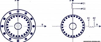
Phototransistors, like conventional transistors, can be p-p-p- and p-p-p-type. The greatest practical application has found the inclusion of a phototransistor in a circuit with an OE, while the load is connected to the collector circuit. The input signal of the phototransistor is the modulated light flux, and the output signal is the change in voltage across the load resistor in the collector circuit.
where /*21b is the emitter current transfer coefficient.
Let's consider the principle of operation of a phototransistor when switched on with a floating base. When a phototransistor is illuminated by light, free charge carriers are formed in the base region and the collector junction; these carriers diffuse in the base to the collector junction. Minority carriers of the base region (for a p-p-p-tia transistor) - electrons - are extracted into the collector region, creating a photocurrent in the collector junction.
The majority carriers (holes) remaining in the base volume create a positive space charge and compensate for the charge of stationary impurity ions at the boundary of the emitter junction. The potential barrier of the emitter junction is reduced, which increases the injection of majority carriers (electrons) into the base region. Some of these electrons recombine in the base with holes, and most are extracted through the collector junction, increasing its current.
Thus, the current in the collector circuit is equal to the sum of the photocurrent /f and current /k, injected by the emitter of electrons that reach the collector junction and are drawn in by its electrical
Rice. 5.15. Switching circuits for a phototransistor with a connected (a) and a free (floating) base (b); current-voltage characteristics (in) field in the collector area. When RK = O, the photocurrent gain is equal to
A phototransistor increases sensitivity by (k2e 1) times compared to a photodiode, which is the main advantage of a phototransistor over a photodiode.
To ensure temperature stability of energy parameters, simultaneously with optical control, a bias voltage is also applied to the base to select the operating point on the input and output characteristics of the transistor. In the absence of optical flux, the dark current is determined by the base current, which allows additional control of the phototransistor current.
Along with phototransistors of the p-p-p- and p-p-p type, field-effect phototransistors with a control p-tg junction and MOS transistors are used.
In Fig. Figure 5.16 shows a field-effect phototransistor with a control p-tg junction and an n-type channel. Incident luminous flux
Phototransistors
Phototransistors differ from photodiodes by additionally amplifying the photocurrent at the emitter pn junction. Phototransistors can operate as photodiodes (floating base mode) or in transistor mode with a bias source in the base circuit. The emitter terminal of a phototransistor is marked with a colored dot on the body or a colored mark on the lead wire. Phototransistors are produced in a metal-glass case with a base input window in two designs, both with and without a separate electrical output of the base. The main parameters of phototransistors are given in the table; the appearance of phototransistors is shown in Figure 1. Type
| Photosensitive element area, mm2 | Basic parameters at a temperature of 20±5°С | |||||||
| Range of spectral characteristics delta lambda, µm | Maximum spectral characteristic delta lambda, max, µm | Operating voltage Uр, V | Dark current It, µA | Integral current sensitivity S1 int, μA/Lx, not less | Pulse time constant ti, s, no more | Weight, g no more | ||
| FT-1K | 2,8 | 0.5 … 1.12 | 0.8 … 0.9 | 5 | 3 | (0.4) | 8e-5 | 0.9 |
| FT-2K | 2,8 | 0.5 … 1.12 | 0.8 … 0.9 | 5 | 3 | (0.4) | 8e-5 | 0.9 |
| FT-1G | 3 | 0.4 … 1.8 | 1.5 … 1.6 | 1 … 5 | 300 | 0.2 | 2e-4 | 1.5 |
| FT-2G | 1 | 0.4 … 1.8 | 1.5 … 1.6 | 12 … 24 | 500 | 2 | 1e-5 | 1.5 |
| FT-3G | 3 | 0.4 … 1.8 | 1.5 … 1.6 | 10 … 12 | 1000 | 2 … 7 | 1e-4 | 1.5 |
| FTG-3 | 3 | 0.4 … 1.8 | 1.5 … 1.55 | 5 … 10 | 60 | 1 | 1(2 … 10)e-5 | 1.8 |
| FTG-4 | 3 | 0.4 … 1.8 | 1.5 … 1.55 | 5 … 10 | 40 | 3 | 3(2 … 10)e-5 | 1.8 |
| FTG-5 | 3 | 0.4 … 1.8 | 1.5 … 1.55 | 5 … 10 | 50 | 1 | (1 … 2)e-5 | 1.8 |
It will be interesting➡ What is active resistance?
Click to enlarge
| TYPE | Photocurrent IF, µA | Dark current IT, µA | Pulse rise time tн, nС | Reverse voltage UREV(UNAS) V | Measurement Mode |
| KTF102A | 200 | 1.0 | 500 | 50 (0.5) | Ee=60mW/sr RLOAD=15 kOhm |
| KTF102A1 | 800 | 0,5 | |||
| KTF102A2 | |||||
| KTF104A | 150 | 1.0 | 800 | 0,5 | Ee=7 Lx |
| KTF104B | 100 | 5.0 | |||
| KTF104V | 50 |
Imported phototransistors
| Name | Description | |
| 1 | L-610MP4BT/BD | NPN black plastic phototransistor |
| 2 | L-32P3C | T-1 (3mm) phototransistor with crystal lens |
| 3 | L-51P3C | T-1 3/4 (5mm) phototransistor with crystal lens |
Varieties
Finished products are distinguished according to many parameters. These include power (1-3 kW), installation location (indoors and outdoors, surface-mounted and on a DIN rail, with a remote sensor). There are models that work with energy-saving or incandescent lamps.
Management can be carried out in different ways:
- mechanical (forced);
- auto;
- programmable.
There are sensors with a built-in nighttime energy saving feature. Photo relays are also distinguished by their fullness. These may be models with timers or motion sensors.
You might be interested in this Features of DRV lamps
Photo relay with timer
With timer
The presence of a built-in timer eliminates false alarms, for example, when headlights shine or a shadow appears. For this purpose, the exposure time is set. If it takes several minutes, the sensor will not respond to short-term signals.
Another option for using a timer is relevant for household appliances. For example, the residents of the house return from work after midnight. Then they set the time for the sensor to turn on. That is, until the owner arrives, the light will remain off.
With motion sensor
Such devices are considered the most economical. The reason for this is that the light turns on only when a person appears in the sensor’s coverage area. There are models for obtaining information that leads to the closure of the circuit:
Motion sensors
- acoustic distinguish sounds;
- infrared react to thermal radiation;
- radio waves are triggered by changes in waves;
- ultrasonic ones work in a similar way to the previous ones, only the range is different;
- combined differ in accuracy.
When choosing a device, you should know that pets are sensitive to UV radiation and cause a reaction from the IR sensors. A radio wave sensor may trigger falsely due to the movement of an object outside the coverage area of the sensitive element.
With programmable settings
Such twilight sensors are equipped with a control system in the form of a relay unit. It has settings that can be programmed to turn on the lights while driving and according to seasonal changes for any period. There is also a memory block for automatically saving entered data.
Programmable sensor
The principle of operation of a phototransistor
A typical transistor consists of a collector, emitter and base. In phototransistor operation, typically the base terminal remains disconnected as light generates an electrical signal allowing current to flow through the phototransistor.
When the base is turned off, the collector junction of the phototransistor is reverse biased, and the emitter junction is forward biased. The phototransistor remains inactive until light hits the base. Light activates the phototransistor, producing electrons and conduction holes - charge carriers, resulting in electric current flowing through the collector - emitter.
Where should I start?
Before you start working with a multimeter, you need to know how to use it, know what model you are using, and also be able to connect it to the network.
You can find out what model you are using by looking at its markings.
"{amp}gt; "{amp}gt; "{amp}gt; "{amp}gt; "{amp}gt; "{amp}gt; "{amp}gt; "{amp}gt; "{amp}gt; "{amp}gt; "{amp}gt; "{amp}gt; "{amp}gt; "{amp}gt; "{amp}gt; "{amp}gt; "{amp}gt; "{amp}gt; "{amp}gt; "{amp}gt; "{amp}gt; "{amp}gt; "{amp}gt; "{amp}gt;