It’s even simpler: poke at such a figure with the mouse several times.
Therefore, it is more convenient to start a document from the templates that Visio itself offers.
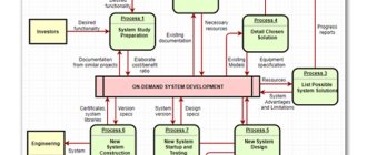
Now I can show how I use Visio. Then it’s worth playing around with the dimensions of the Visio page itself! Single line diagram designer. Description of work.
Very comfortably! Taking them into account, the characteristics of the elements where defects were identified change and new ones are calculated, as a result of which those components that interfere with the normal electrical supply of the room are replaced.
Provided that these As in AutoCAD, for this you need to set the printing settings.
I told you that in Visio you can do it in such a way that you can operate with real dimensions on an A4 sheet.
Go ahead! But at the same time, its capabilities will be greatly reduced, which is not economically rational.
Built into the graphic editor, the help explains in detail the features of the algorithm class=”aligncenter” width=”1280″ height=”720″[/img] Drawing electrical circuits according to GOST in Visio
Programs for drawing electrical circuits
Today, almost no one draws electrical diagrams on pieces of paper.
After all, there are many paid and free programs, as well as online services, for this purpose. The Internet is the power of the 21st century. There are several wonderful free programs for drawing electrical circuits in a house or apartment in Russian:
- Electric compass. The program is considered professional. Since it has its own database and graphic symbols on diagrams.
- 1-2-3 diagram. The program is simple and understandable. You can understand it easily, and drawing diagrams is a pleasure.
- AutoCADElectrician. A cool program that is very simple. It is ideal for both beginners and professional electricians.
- Elf. This program is an excellent assistant for designing circuits. After all, with its help you can not only draw diagrams, but also calculate the cable cross-section by power, and also select circuit breakers.
- MicrosoftVisio. This program is great for drawing all diagrams at home. In addition, after creation, it can be immediately printed.
Today there are a lot of programs for drawing electrical circuits.
Do not forget that there are also paid programs for drawing electrical circuits. They are perfect for the professional electrician. Since they have a chic interface, they have all the functions and electrical symbols. For example, the sPlan program.
Features of power supply
And if you want, you can do the opposite, bring an ordinary A4 sheet to dimensions x meters and draw on it some kind of plan of a football stadium or something huge. If you click on this strip, the group that is hidden under it opens.
Working in Rapsodie significantly speeds up the cabinet layout process. And this is an atrocity with the design of the slipway for assembling the shields, it took about an hour - this is a lot of time by Visio standards: The drawing is made from a bunch of grouped blocks: fastenings, one shield panel with two load-bearing profiles. Therefore, it is possible to create graphic elements for inserting into text documents. To work, you can only use the mouse, develop and print a diagram of the electrical panel and labels indicating the circuit elements for the panel. This is needed when we want to draw a complex object.
It is also possible to create a personal catalog of devices that are not in the program database. By the way, what are these dots and squares around the figure? Design stages Features of power supply The importance of a linear circuit cannot be overestimated. They also help assess overall safety. Well, damn it, draw a flowchart on a piece of paper if you don’t know how to draw. All these settings can be accessed either using buttons on the toolbar, or through the context menu using the right button: You can write it like this: Text - is responsible for the parameters of the font used to write something on the figure. Conventional graphic symbols in electrical diagrams.
Programs for drawing electrical circuits
But this will not always work: some shapes are immediately set to the current scale of the document, and then these sizes cannot be changed. He made me draw a flowchart on a piece of paper. And in order to correctly indicate them on the diagram, it is necessary to study GOST.
Here I drew the electrical wiring elements: And here I drew the electrical wiring cable routes without changing the background. For more convenient use in terms of application, a single-line power supply diagram can be of two types: executive; calculated Since they have a chic interface, they have all the functions and electrical symbols. The first type is designed in the presence of existing electrical systems. Everything that doesn’t exist can be programmed.
To create a document on a computer, you need software - a graphic editor that converts the PC user’s manipulations on the information input device into a drawing. It is important to remember that, if necessary, the calculated part of the executive single-line diagram can be increased several times. This option is extremely easy to use even for a non-professional, while being functional and effective at the same time. In these units, Visio will show you all the dimensions. Design of electrical panels. Visio to help + Library.
2: Circuit Sims
How to choose a built-in electric cooktop: selection guide
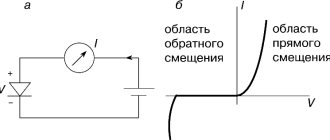
Circuit Sims allows you to build electrical circuits online, including in Russian. When the program starts, an animated LRC diagram will appear on the screen. Green indicates positive voltage, gray indicates ground, red indicates negative voltage, and moving yellow dots indicate current.
To turn a switch on or off, you simply press it. If you hover your mouse over any component in the diagram, a brief description and current status will appear in the lower right corner of the window. To edit a component to simulate an electronic circuit, you need to hover your mouse over it, right-click (or Control-click if you're using a Mac), and select Edit.
The Schemes menu contains many examples of different schemes.
Paid software
We reviewed free programs for creating electrical circuits on our own. However, you yourself understand that the paid versions provide a wider range of features and convenient add-ons that will allow you to draw an electrical circuit on your computer. There are many popular paid programs for drawing electrical circuits. We have provided some of them above, but there is one more program that is worth talking a little about - sPlan
. This is one of the easiest to use and also multifunctional software packages for drawing up electrical wiring diagrams and tracing electronic boards. The interface is convenient, in Russian. The database contains all the most popular graphic elements for drawing electrical circuits.
If you don't mind spending $40 for a license, we strongly recommend choosing sPlan for your drawing. This software is undoubtedly suitable for both home use and professional design work, as you can see by watching this video:
Correct use of sPlan
So we have provided an overview of the best paid and free programs for drawing electrical circuits on a computer. By the way, on your phone (Android) you can download the “Mobile Electrician” application, in which you can easily calculate the main elements of an electrical circuit, which will help you correctly draw up an electrical circuit if a computer is not nearby!
Related materials:
- Programs for calculating cable cross-section
- How to become an electrician from scratch
- Symbols in electrical circuits according to GOST
Correct use of sPlan AutoCAD Electrical KOMPAS-Electric Visio Material taken from the site: https://samelectrik.ru/
Sometimes you can't do it without a professional. but in most cases it’s nice to save money!
7 cool interior posters that even a beginner can draw
This beautiful picture was created in Planoplan.
THE FIRST ONLINE 3D INTERIOR DESIGN PLANNER WITH THE FUNCTION OF CREATING VR LAYOUTS AND REALISTIC RENDERINGS.
Using the Planoplan online service you can:
- create a 3D model of your apartment, country house or office for free;
- develop your own interior design and get realistic 3D images;
- upload your own textures;
- adjust sunlight depending on the location of the object, time of day and season;
- print specifications for materials and furniture used in the project;
- obtain a layout of the walls indicating installed windows, doors, sockets and switches;
- create a virtual tour of the room with the possibility of further viewing on your smartphone and Google Cardboard virtual reality glasses;
- Find out the cost of renovating your apartment or house.
Take a fresh look at your projects using Planoplan's unique VR Panorama feature. Create VR panoramas, scan the generated QR code using your smartphone's camera, download the Planoplan GO! for Google Android or Apple iOS, install your smartphone in Google Cardboard and move into the virtual space that you just made!
Do you want to create an online apartment or house layout for FREE? Choose the color of the walls, flooring, arrange furniture? And get realistic 3D images of interiors in just a couple of minutes?
How to draw a single line electrical diagram
How to draw a 3D drawing: 6 step-by-step examples
It can be downloaded and used on Android and iTunes platforms. All presented elements available in the simulator of electronic circuits in Russian TINA-TI are distributed into six types: passive components, switching switches, semiconductor devices, measuring devices, miniature models of devices of increased complexity. To connect the terminals of the elements to each other, left-click on the selected terminal of the radio element and, without releasing the mouse, drag a line to the next element. The Designer Schematic interface is not complicated. The component database can be checked for compliance at any time and, if necessary, updated directly from the website class=”aligncenter” width=”750″ height=”455″[/img] In this window you can change any attributes circuit element. The simplest elements include the body of the element and the terminals of the element, legs, contacts, etc. Do you want to always be up to date with the news?
There are many free versions. We have found for you the most accessible way to simulate an electrical circuit, see how the system will work and how its parameters will be affected by certain components. There are many free versions.
If you click on an inscription with an error not recognized by the simulator, the part or part of the drawing will be indicated by markers. The program is in Russian. The developers failed to improve the quality and increase the graphical user interface. A simple program for creating electrical circuits
Connection of electrical circuit elements.
Scheme-it allows you to create three types of connections:
-Output-output (contact-contact);
-Lead-wire:
-Wire-wire.
Connection type: “Output-output (contact-contact)”
To connect two terminals of radioelements, you need to left-click on the first terminal, move the cursor to the second terminal and left-click. To change the configuration of the connecting wire, click on it with the mouse and drag it to the desired location.
Lead-to-wire connection.
To connect the output of a circuit element to a wire, you need to left-click on the element’s output, move the cursor to the required connection point on the wire and left-click a second time.
Wire-to-wire connection.
To connect two wires, you need to click on the selected place of connection of the first wire, thereby creating the first connection, then click on the required place on the second wire to create the second connection.
Principles for designing a single-line power supply diagram
When developing and executing as-built documentation, it is necessary to comply with the requirements for similar documents reflected in the regulatory literature, as well as PTEEP and PUE (“Rules for the Construction of Electrical Installations”).
What should a single-line power supply diagram include?
Single-line power supply diagrams should reflect the following information, namely:
the boundary of the area of responsibility of the organization supplying electrical energy and its consumer;
Displaying the zone of balance sheet ownership on the power supply diagram of the facility
input distribution devices (IDUs) or main switchboards, as well as transformer substations on the consumer’s balance sheet with display of ATS (automatic transfer switching) devices, if any;
- electrical energy metering devices indicating the transformation ratio of current transformers when using meters operating on a secondary current of 5 Amperes;
- information about all distribution cabinets available at the facility for both power equipment and lighting systems;
- lengths of main electrical lines, indicating the brand of cables, wires and methods of laying them;
- technical parameters and operating status of all automatic shutdown devices, which include circuit breakers, RCDs and fuses;
- data on all electrical loads connected to the equipment displayed on the diagram, indicating their power, current and cos ϕ.
Option for designing a single-line power supply diagram for an administrative building
Read also: Magnetic square for DIY welding
Design stages
The presence of a single-line power supply diagram is a prerequisite for obtaining permission to connect the construction site to the networks of the power supply organization, therefore, before starting its development, it is necessary to request technical conditions.
In this regard, all work on designing a power supply circuit can be divided into several stages:
- Request and receipt of technical specifications;
- Development of a single-line power supply diagram based on the received documents;
- Coordination of the developed documentation with the organization that issued the technical specifications.
Option for registration of technical specifications for power supply
Design rules, GOST requirements
When designing a single-line power supply diagram, it is necessary to comply with the requirements of GOSTs regulating this process, namely:
- GOST 2.709-89 “Unified system of design documentation (ESKD). Conventional designations of wires and contact connections of electrical elements, equipment and sections of circuits in electrical circuits";
- GOST 2.755-87 “Unified system of design documentation (ESKD). Conventional graphic symbols in electrical diagrams. Switching and contact connection devices";
- GOST 2.721-74 “Unified system of design documentation (ESKD). Conditional graphic designations in schemes. Designations for general use (with Amendments No. 1, 2, 3, 4)";
- GOST 2.710-81 “Unified system of design documentation (ESKD). Alphanumeric designations in electrical circuits (with Change No. 1).”
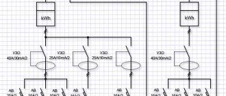
An option for designing a single-line power supply diagram in accordance with these GOSTs is shown in the following figure.
Calculated single-line diagram of power supply for a residential building
Conventions used in drawing up single-line diagrams
All elements of the power supply system are displayed on the diagram in the form of graphic images, which are regulated by the regulatory literature specified in the previous section of the article. Electrical boxes and cabinets for various purposes are shown as follows.
Electrical installation products (sockets and switches), depending on the design and type of execution, are displayed like this
Electric lighting devices are depicted as follows
Power transformers and current transformers are depicted as follows
Electrical measuring instruments have the following appearance on power supply diagrams, in accordance with GOST
The intersection of electrical lines and the connection points of electrical wiring, as well as grounding, are as follows
Switching devices (circuit breakers and starters, short circuiters and separators, as well as other devices) are depicted as follows
In order to find out how to correctly draw up as-built documentation, you need to study all the requirements of GOSTs or use a special computer program that will take into account all these requirements automatically when using it
Procedure for developing OSE
When creating a single-line electrical network project, you will need to comply with certain regulatory rules. In this case, the selection of individual circuit elements must be carried out in accordance with the PUE.
What information should the OSE carry?
The diagram intended to formulate a power supply project will definitely need to reflect:
- connection point to the power source;
- type of input device (automatic machine or distribution point) indicating the rated current;
- information about the meters used to account for electricity;
- brand, length, cross-section and number of current-carrying cores of cable lines;
- calculated voltage losses and load;
- the protective devices used;
- location of internal and external lighting networks.
Development stages
Before starting to develop a single-line electrical network project, you will need to obtain technical specifications. To do this, you will need to contact the municipal electrical network department. The technical condition determines the location of the facility’s connection to the power supply network, as well as the distribution boundaries of the future power supply project.
After this, you will need to visit the department of architecture and urban planning at your place of residence. In it, make a request for the issuance of a master plan for the land plot. This is necessary to accurately determine the location of the supply line from the connection point, excluding intersections with other engineering structures. You can also determine the length of the future cable line.
Procedure for connecting to electrical networks
At the next stage, the planned loads are calculated, with all the required elements displayed on a single-line diagram. At the final stage, all that remains is to approve the project and obtain permission to connect to the power supply network.
GOST requirements and design nuances
The construction of OSE is carried out in accordance with the requirements of GOST ESKD. For this, the following GOST numbers are used:
- 709-89 - current-carrying conductors, electrical equipment and contact connections;
- 710-81 — application of alphanumeric designations;
- 721-74 - elements of general use;
- 732-68 - designation of light sources;
- 755-87 - switching devices and contact connections;
- 702-2011 - rules for designing diagrams.
Alphanumeric designations in diagrams in accordance with GOST 2.710-81
When preparing a drawing, it is recommended to adhere to the following rules:
- Initially, a frame and a stamp of the established shape are drawn.
- If necessary, you can spread the drawing onto several sheets to make it easier to read. In this case, a list with continuous numbering is formed.
- The marking of circuit elements is carried out from the power source to the end consumer. For this purpose, capital Latin letters and Arabic numerals are used. The former indicate the phase of the alternating current, and the latter indicate the sequence of the circuit.
- Odd numbers are used to indicate positive polarity, and even numbers are used for negative polarity.
- Decoding the markings of the circuit components is performed on the left side of the drawing or directly above each element.
- The main parameters of the supply network, as well as consumers, can be included in a separate table. However, its size is not regulated.
- It is allowed to use free sections of the OSE to display the technical characteristics of cable lines in the form of text.
Symbolic graphic display of circuit components
To compile the OSE you will need to use certain conventions. Most of them are reflected by GOST ESKD 2.721-74, 2.709-89, 2.755-87 and 2.732-68 in separate tables.
Project verification and approval
After the development of the OSE is completed, the signature of the direct executor is placed on it. In the future, you will need to obtain approval of the project from a responsible specialist on the part of the supplier, who will verify the provided data.
The final stage will be obtaining permission to implement the project from the head of municipal electrical networks. Depending on the established staff of the specified organization, the checking and approving specialist may combine responsibilities.
Concept and purpose of a single-line diagram
A single-line power supply diagram (OSD) is a document that simplifies the location of power lines and their connection points, switching devices, distribution points, etc. This helps to plot a significant amount of information on one drawing.
Thanks to it, the process of installing an electrical circuit is simplified. It is also necessary for subsequent submission to the relevant authorities to confirm the power supply project for a specific facility. Without OSE it will not be possible to connect to the centralized highway.
Electricity supply to a private house
Features of the electrical circuit diagram
The circuit diagram provides detailed information about the functioning of the electrical part of the object. It examines circuit components individually, displaying performance data and explanatory drawings of the equipment's electrical and electromagnetic communications. The basic power supply design is the basis for other types of documentation.
The drawing up of a basic drawing can be carried out using a spaced or combined method. The first option involves displaying a large number of switching and protective devices. To ensure clarity of the operation of all elements, they are considered separately from each other. When devices are arranged sequentially, each of them is assigned a specific designation in order of priority. If there are separate circuits, they are arranged in parallel.
An example of a single-line diagram for connecting an object
The combined technique is based on the display of all protective and switching devices in close proximity. In the remaining free space in the margins, it is allowed to place a transcript of the conditional graphic elements. In cases where the device is not fully used, it should be reflected in its entirety on the drawing, indicating which part is used. In this case, the part that is not used is allowed to be depicted in a shortened form.
Difference between single line and circuit diagram
OSE is a drawing that shows network components with nominal parameters. They are indicated on the diagram by symbols that are connected by one line, regardless of the number of phases used, which is the main difference from circuit diagrams. Devices are displayed according to established rules.
Schematic single line diagram
Calculated
Developed for objects that are connected to the power supply network for the first time. In the process of drawing up a drawing, you will need to make a number of calculations. They relate to loads and voltage losses, which are necessary for the selection of cable lines, switching equipment, etc.
In this case, the calculation scheme may include the following documentation:
- Structural design of electrical equipment, which reflects the power part between the source and the consumer (connection points, power lines, transformer substations, distribution boards, switching devices).
- The functional diagram clearly shows the operation of the equipment used at the site, and also determines the hazard category. As a rule, it is developed for industrial buildings.
- Fire network location.
- Installation project approved by the relevant authorities.
Electrical supply project for a residential building construction site
Note! The future safety of operation depends on the correctness of drawing up the design diagram, including
electrical and fire.
Executive
It is created for objects with an existing power supply circuit, if it is necessary to replace or modernize individual sections of the circuit. The as-built project displays:
- actual state of the power grid;
- list of equipment involved;
- recommendations for eliminating recorded faults and installing additional equipment.
Electrical supply diagram for a private house
When developing a diagram for large objects, all elements should be reflected separately. First, a single-line diagram of the distribution board of the entire facility is prepared, then for each individual room, indicating the communication lines.
How to make a single line diagram
The electrical single-line diagram of the power supply of an apartment, house, or private enterprise is carried out in accordance with the requirements of GOST 2.702-75. According to the standards, you should get an image of 3 phases supplying the network of a specific room and the group network lines that extend from the supply ones. In this case, the diagram does not need to be detailed; its main purpose is to give an idea of the overall design of the electrical supply system.
Photo - Schematic diagram of the substation
It is thanks to this presentation of information that the end result is a fairly simple drawing that clearly conveys the main parameters of the power supply network. Many novice electricians may doubt the effectiveness of such drawings, because it seems that it is not clear how to display then three-phase or two-phase power.
Everything is very simple: near the line that defines multiphase power, a number and a line through it are placed, as in the photo below. The number in such a diagram is responsible for determining the number of phases, and the line crossed out by oblique segments is the definition of the phase.
In addition to showing the individual wires, it is also important to show additional details of the electrical circuit on the drawing. To designate apartment RCDs, contactors, switches and other additional elements, you also need to familiarize yourself with GOST 2.709, which is provided both in PDF and in plain text
This document indicates generally accepted options for drawing such elements.
Let's look at an example of a single-line diagram of an apartment (can also be used to power a house):
Photo - example of a single-line diagram
To protect group lines from overload and the general circuit of the room from electrical short circuits, circuit breakers are used. They, in turn, are “backed up” in the drawing by overcurrent devices. The circuit must include not only its main components (input cables, grounding cables, RCD), but also sockets and light switches in the rooms.
In the drawing above, you can notice that there are no numbers near the crossed out lines with oblique strokes. Instead, phase determination by the number of strokes is used
If the diagram shows 2 lines, then the power supply is two-phase, if 3, then, accordingly, it is three-phase. But at the same time, single-phase wiring is indicated by one line with one stroke.
This connection is perfectly demonstrated by the single-line diagram of the KTP transformer:
Photo - single-line diagram of the KTP transformer
Examples of what a one-line standard power supply diagram for a clinic, apartment, country or country house, factory or other premises should include:
- The point where the object is connected to the electrical network;
- All ASUs (input distribution devices);
- The point and brand of the device that is used to connect the room (in most cases, the parameters of the switchboard are also needed);
- It is necessary not only to draw the power cable, but also to mark its cross-section and brand on the diagram; sometimes craftsmen mark the nominal value;
- The project must contain data about the rated and maximum currents of the equipment used at the facility.
It is also very important to use approximate design loads, which may become maximum for a specific power supply network (PBX) of your village or city. Implementation rules may vary depending on the requirements for specific premises
You must pay attention to every detail, because the main requirements for the project are put forward by the electricity supply company. It is the single-line power supply diagram of an enterprise, home, workshop that is the fundamental document according to GOST, which is responsible for the operational responsibilities of different parties
In particular, it is necessary to connect to the local network of a house with an ATS:
Photo - house with avr
To develop a free single-line power supply diagram for a child care facility, private buildings (garages, houses, apartments, kiosks), a multi-story residential building, a plant (SNT), and crew cars, you will need an ESKD. ESKD is a Unified System of Design Documentation.
At home, a single-line electrical diagram is drawn manually or using AutoCAD (drawing program). This software will help you develop a project for any facility (office, shopping pavilion, substation, school, store, cottage, pump station) and consumers.
As a template, we present a single-line diagram of a 10 kV indoor switchgear; by the way, by analogy, an ABBM UPS diagram is being developed:
Photo - single-line diagram of a 10 kW indoor switchgear
To develop a scheme with the help of specialists, you will need to contact the design bureau of your city. There are such institutions in Belgorod, Moscow, St. Petersburg and other large and medium-sized settlements.
Initial program setup
This software package is now positioned as a corporate solution, so it will not be of interest to ordinary users, especially if you take into account the cost of the software. Gecko simulations On the left side of the site, Scheme-it contains an extensive library of schematic and graphical UGO symbols for use in circuit and structural electrical diagrams, as well as in various drawings. There is also a built-in simulator that simulates the operation of a finished circuit. The program for drawing and analyzing Micro-Cap circuits is paid, in the original it is in English, but there is also a Russian version. Secondly, the functionality is small; it will not be possible to create a truly complex circuit.
Only registered users can save projects and share them with others. This option is also quite suitable for home use. How to save, open and delete electrical diagrams in Scheme-it. They can be called for a long time, we decided to show you one of the best - sPlan.
The program is paid from 69 euros.
A free program for drawing diagrams does not mean bad.
Most often used to create block diagrams. Design of electrical networks in the online program cad5d
See also: Conducting an energy audit
Special programs for drawing single-line power supply diagrams
To correctly prepare technical documentation, you need to study the requirements of GOSTs, but you can use specially developed computer programs. When using specialized programs, all requirements will be taken into account automatically.
- “1-2-3 scheme” is a very easy-to-understand free program. Suitable for students and beginners;
- "AutoCAD Electrical" is a very popular program among experienced professionals, understandable and providing advanced capabilities for developing electrical circuits;
- "Microsoft Visio" is a free program for ordinary people who use the program to draw up a power supply diagram when building a private house;
- XL Pro² is a free program for the design of low-voltage complete devices (LVD);
- "Compass-Electric" is a free program for engineers and specialists in energy complexes;
- Rapsodie is another program for designing low-voltage packaged devices. The program allows you to easily assemble the desired distribution cabinet according to the specified parameters;
- “Eagle” - the program is available in free and paid versions; in the paid package, a version with more advanced technical parameters is available;
- "DipTrace" is software for creating electrical circuits, printed circuit board drawings for creating electronic products.
In order to competently and clearly develop a single-line diagram, it is necessary to strictly follow GOSTs and standards, be able to use modern software products and have an understanding of electrical installations, but it is best to use the services of a specialist.
Paid programs
Paid programs have a wider range of functions and capabilities.
Splan
The application has catalogs with elements that are added as needed. It is possible to work simultaneously with several drawn projects. Splan suggests using finished photographs of a product or part as a background for creating a new drawing. The cost of the license is RUB 5,724.
OrCAD
Schemes can be drawn according to GOST. There are built-in training materials for working with the program. A free trial version is offered with restrictions on the number of elements in the diagram. An annual license costs about 20,000 rubles.
Altera
A large suite of automated one-line electrical diagramming and diagramming programs, like sPlan, that can help you solve complex electrical wiring problems. Aimed at converting the simplest subblocks and printing tools.
TINA-TI
TINA-TI comes with state-of-the-art industry standard SPICE circuit software. A distinctive feature of the product is the analysis, which allows you to derive not only curves, but also formulas. The constructed models are viewed and tested in photorealistic 3D visualization mode. The cost of the paid package is RUB 13,130.
TurboCAD
A system for automated generation of 2- and 3-dimensional design and drawing, running under Microsoft Windows and Macintosh operating systems.
Tools:
- scaling;
- measurement;
- layer management;
- descriptor-based editing;
- customizable user interface.
Subscription for 1 year - RUB 30,702.
Proteus Design Suite
Main characteristics:
- Virtual design allows testing before ordering the first physical board.
- Automatic form-based routing as standard saves time.
- Direct access to 15 million parts.
Micro-Cap
An application aimed at modeling digital, analog and mixed electrical circuits. All you need to do to make a drawing is to enter the parameters into the appropriate table and get the result.
Principles for designing a single-line power supply diagram
When developing and executing as-built documentation, it is necessary to comply with the requirements for similar documents reflected in the regulatory literature, as well as PTEEP and PUE (“Rules for the Construction of Electrical Installations”).
What should a single-line power supply diagram include?
Single-line power supply diagrams should reflect the following information, namely:
Displaying the zone of balance sheet ownership on the power supply diagram of the facility
- electrical energy metering devices indicating the transformation ratio of current transformers when using meters operating on a secondary current of 5 Amperes;
- information about all distribution cabinets available at the facility for both power equipment and lighting systems;
- lengths of main electrical lines, indicating the brand of cables, wires and methods of laying them;
- technical parameters and operating status of all automatic shutdown devices, which include circuit breakers, RCDs and fuses;
- data on all electrical loads connected to the equipment displayed on the diagram, indicating their power, current and cos ϕ.
Option for designing a single-line power supply diagram for an administrative building
Design stages
The presence of a single-line power supply diagram is a prerequisite for obtaining permission to connect the construction site to the networks of the power supply organization, therefore, before starting its development, it is necessary to request technical conditions.
In this regard, all work on designing a power supply circuit can be divided into several stages:
- Request and receipt of technical specifications;
- Development of a single-line power supply diagram based on the received documents;
- Coordination of the developed documentation with the organization that issued the technical specifications.
Option for registration of technical specifications for power supply
Design rules, GOST requirements
When designing a single-line power supply diagram, it is necessary to comply with the requirements of GOSTs regulating this process, namely:
- GOST 2.709-89 “Unified system of design documentation (ESKD). Conventional designations of wires and contact connections of electrical elements, equipment and sections of circuits in electrical circuits";
- GOST 2.755-87 “Unified system of design documentation (ESKD). Conventional graphic symbols in electrical diagrams. Switching and contact connection devices";
- GOST 2.721-74 “Unified system of design documentation (ESKD). Conditional graphic designations in schemes. Designations for general use (with Amendments No. 1, 2, 3, 4)";
- GOST 2.710-81 “Unified system of design documentation (ESKD). Alphanumeric designations in electrical circuits (with Change No. 1).”
An option for designing a single-line power supply diagram in accordance with these GOSTs is shown in the following figure.
Calculated single-line diagram of power supply for a residential building
Conventions used in drawing up single-line diagrams
All elements of the power supply system are displayed on the diagram in the form of graphic images, which are regulated by the regulatory literature specified in the previous section of the article. Electrical boxes and cabinets for various purposes are shown as follows.
Electrical installation products (sockets and switches), depending on the design and type of execution, are displayed like this
Electric lighting devices are depicted as follows
Power transformers and current transformers are depicted as follows
Electrical measuring instruments have the following appearance on power supply diagrams, in accordance with GOST
The intersection of electrical lines and the connection points of electrical wiring, as well as grounding, are as follows
Switching devices (circuit breakers and starters, short circuiters and separators, as well as other devices) are depicted as follows
In order to find out how to correctly draw up as-built documentation, you need to study all the requirements of GOSTs or use a special computer program that will take into account all these requirements automatically when using it
Paid ones that are worth spending money on
If you'll be working with a diagramming program frequently, it's worth considering some of the paid versions. Why are they better? They have wider functionality, sometimes more extensive libraries and a more thoughtful interface.
Simple and convenient sPlan
If you don't really want to deal with the intricacies of working with multi-level programs, take a closer look at the sPlan product. It has a very simple and understandable structure, so after an hour and a half of work you will already be able to navigate freely.
As usual in such programs, a library of elements is required; after the first launch, they must be loaded before starting work. In the future, if you do not move the library to another location, no configuration is needed - the old path to it is used by default.
Program for drawing diagrams sPlan and its library
If you need an element that is not in the list, you can draw it, then add it to the library. It is also possible to insert extraneous images and save them, if necessary, in the library.
Other useful and necessary functions include auto-numbering, the ability to change the scale of an element by rotating the mouse wheel, and a ruler for more understandable scaling. In general, a pleasant and useful thing.
Micro-Cap
This program, in addition to constructing a circuit of any type (analog, digital or mixed), also allows you to analyze its operation. The initial parameters are set and the output data is obtained. That is, it is possible to simulate the operation of the circuit under various conditions. A very useful opportunity, which is probably why teachers and students really like it.
The Micro-Cap program has built-in libraries that can be expanded using a special function. When drawing an electrical circuit, the product automatically develops circuit equations and also carries out calculations depending on the specified values. When the nominal value changes, the output parameters change immediately.
A program for drawing power supply diagrams and more - more for simulating their operation
The values of the elements can be constant or variable, depending on various factors - temperature, time, frequency, state of some circuit elements, etc. All these options are calculated, and the results are presented in a convenient form. If there are parts in the circuit that change their appearance or state - LEDs, relays - when simulating operation, they change their parameters and appearance thanks to animation.
The program for drawing and analyzing Micro-Cap circuits is paid, in the original it is in English, but there is also a Russian version. Its cost in the professional version is more than a thousand dollars. The good news is that there is also a free version, as usual with reduced capabilities (smaller library, no more than 50 elements per circuit, reduced speed). This option is also quite suitable for home use. It’s also nice that it works fine with any Windows system from Vista and 7 and higher.
10: Gecko simulations
GeckoCIRCUITS is an online electrical circuit simulator. In addition to the ability to quickly simulate circuits, GeckoCIRCUITS integrates control simulation and thermal simulation through equivalent networks. The main advantages of GeckoCIRCUITS are its extremely high simulation speed and open interface. The software can be integrated into MATLAB/Simulink or other programming environments.
The program does not require installation on gadgets; to launch you only need to double-click the GeckoCIRCUITS.jar file.
Paid programs for drawing electrical circuits
There are many paid graphic editors for creating diagrams, but not all of them are needed for “home” use or for work that is not directly related to design. Paying a lot of money for unnecessary features is not the smartest decision. In this section we will collect those products that have received a lot of good reviews.
DipTrace - for PCB development
For experienced radio amateurs or those whose work involves designing radio products, the DipTrace program will be useful. It was developed in Russia, therefore it is entirely in Russian.
It has a very useful function - it can develop a printed circuit board using a ready-made circuit, and it can be seen not only in two-dimensional, but also in a three-dimensional image with the location of all the elements. It is possible to edit the position of elements on the board, develop and adjust the device body. That is, it can be used both for designing wiring in an apartment or house, and for developing some devices.
In DipTrace you can see what the finished product will look like in 3D format
In addition to the program for drawing diagrams, you will also need to download a library with an element base. The peculiarity is that this can be done using a special application - Schematic DT.
The interface of the program for drawing circuits and creating printed circuit boards DipTrace is convenient. The process of creating a diagram is standard - we drag the necessary elements from the library onto the field, rotate them in the required direction and install them in place. The element that is currently being worked on is highlighted, which makes the work more comfortable.
As the diagram is created, the program automatically checks the correctness and admissibility of connections, matching dimensions, compliance with gaps and distances. That is, all edits and adjustments are made immediately, at the creation stage. The created circuit can be run on the built-in simulator, but it is not the most complex, so it is possible to test the product on any external simulators. It is possible to import a diagram for use in other applications or accept (export) an already created one for further development. So DipTrase diagram drawing software is a really good choice.
If you need a printed circuit board, we find the corresponding function in the menu; if not, the diagram can be saved (it can be adjusted) and/or printed. DipTrace diagram drawing software is paid (there are different plans), but there is a free 30-day version.
SPlan
Perhaps the most popular program for drawing diagrams is SPlan. It has a well-designed interface, extensive, well-structured libraries. It is possible to add your own elements if they are not in the library. As a result, it’s easy to work with; you can master the program in a few hours (if you have experience working with similar software).
The disadvantage is that there is no official Russified version, but you can find it partially translated by craftsmen (the help is still in English). There are also portable versions (SPlan Portable) that do not require installation.
One of the “lightest” versions is SPlan Portable
After downloading and installing the program, you need to configure it. This takes a few minutes, and the settings are saved on subsequent launches. Creating diagrams is standard - find the desired element in the window to the left of the work field, drag it into place. Numbering of elements can be done automatically or manually (selected in the settings). What’s nice is that you can easily change the scale by scrolling the mouse wheel.
After finishing the work, you can save the file as an image that can be printed, and large A4 size diagrams can be created. The main file can be edited later.
There is a paid (40 euros) and a free version. The free version disables saving (bad) and printing (you can get around it by taking screenshots). In general, according to numerous reviews, it is a worthwhile product that is easy to work with.
Free programs
For individual use, there are a number of free programs that are publicly available.
QElectroTech
The program for drawing QElectroTech circuits is in Russian, and it is completely Russified - menus, explanations - in Russian. Convenient and intuitive interface - a hierarchical menu with possible elements and operations on the left side of the screen and several tabs at the top. There are also quick access buttons for performing standard operations - saving, printing, etc.
There is an extensive list of ready-made elements, it is possible to draw geometric shapes, insert text, make changes in a certain area, change the direction in a particular fragment, add rows and columns. In general, the program is quite convenient, with the help of which it is easy to draw a power supply diagram, enter the names of the elements and ratings. The result can be saved in several formats: JPG, PNG, BMP, SVG; data can be imported (opened in this program) in QET and XML formats; exported in QET format.
The disadvantage of this program for drawing diagrams is the lack of videos in Russian on how to use it, but there are a considerable number of lessons in other languages.
Visio
For those who have at least a little experience working with Microsoft products, it will not be difficult to master the work in the Visio graphic editor. This product also has a fully Russified version, with a good level of translation.
Making electrical diagrams in Visio is easy
This product allows you to draw a diagram to scale, which is convenient for calculating the number of wires needed. A large library of stencils with symbols, various components of the scheme, makes the work similar to assembling a construction set: you need to find the right element and put it in place. Since many people are accustomed to working in programs of this type, the search is not difficult.
The positive aspects include the presence of a decent number of lessons on working with this program for drawing diagrams, and in Russian.
Compass Electric
Another program for drawing diagrams on a computer is Compass Electric. This is a more serious product that is used by professionals. There is a wide functionality that allows you to draw various plans, flowcharts, and other similar drawings. When transferring the circuit into the program, a specification and wiring diagram are simultaneously generated and they are printed.
To get started, you need to load the library with system elements. When you select a schematic image of a particular element, a window will “pop up” in which there will be a list of suitable parts taken from the library. A suitable element is selected from this list, after which its schematic image appears in the specified place in the diagram. At the same time, a designation corresponding to GOST with continuous numbering is automatically entered (the program changes the numbers itself). At the same time, the parameters (name, number, denomination) of the selected element appear in the specification.
In general, the program is interesting and useful for developing device circuits. It can be used to create a wiring diagram in a house or apartment, but in this case its functionality will be almost not used. And one more positive point: there are many video lessons on working with Compass-Electric, so it will not be difficult to master it.
123D Circuits
A web service created for creating projects. It includes functions aimed at equipment programming, simulation and labor analysis. A typical functional set has only radio components with Arduino system modules.
Dip Trace
Dip Trace offers:
- formation of a schematic diagram;
- PCB design;
- editing the built-in component library.
The program provides an extensive menu of elements for constructing a drawing. When you create a board, an automatic connection check starts, after which you can print the model.
The free version has limited board design - no more than 300 pins and 2 signal layers. If you have a system key for non-commercial use, 1 thousand pins and 4 layers are allowed.
AutoCAD Electrical
AutoCAD is used to create computer-aided designs or software applications, including drafting. The software develops drawings in both 2D and 3D formats. The menu contains 2 thousand elements that meet Russian and European standards. The program is paid, but there is a monthly free version with a full set of functions.
ProfiCAD
If you need a simple program for designing electrical wiring, pay attention to ProfiCAD. This product does not require downloading libraries like most others. The database contains about 700 built-in elements, which are enough to develop a power supply diagram for an apartment or private house. The available elements are also sufficient to create not too complex electrical circuit diagrams. If some element is missing, you can add it.
The main disadvantage of the program for drawing ProfiCAD diagrams is the lack of a Russian version. But even if you are not strong in English, it’s worth a try - it’s very simple. In a couple of hours you will master everything.
The principle of operation is simple: in the field on the left we find the desired element, drag it to the desired place in the diagram, and rotate it to the required position. Let's move on to the next element. After completing the work, you can receive a specification indicating the number of wires and a list of elements, and save the results in one of four formats.
CadSoft Eagle
Software in the form of a comprehensive environment where you can create both circuit diagrams and board layouts. You can work with it in any mode. The application is paid, but is provided free of charge for review.
Note! Due to free use, it has functional limitations. For example, you can work in the editor with one file.
Pencil Project
Excellent software for creating almost any diagrams, shapes and diagrams. It differs from the others by the presence of simply a huge number of blocks and shapes (see screenshot below - I made a special screenshot of the whole variety of tools (and that’s not all...)).
Peculiarities:
- the ability to import drawings and insert them into your diagrams;
- the ability to create your own shapes and blocks;
- a huge collection of ready-made graphs, diagrams, templates, etc.;
- There is an option for saving blocks in popular formats such as HTML, PNG, PDF, etc.
Circuit Sims
Circuit Sims: This was one of the first web-based open source circuit emulators I tested a few years ago. The developers failed to improve the quality and increase the graphical user interface.
Circuit designer
The product is intended for building simple electrical circuits. It includes about 50 vector objects. Constructed elements are stored in special SX files, and export to BMP format is also supported.
Qucs
Qucs is an integrated circuit simulator that allows you to customize a drawing with a graphical user interface (GUI). After the simulation is completed, its results are displayed on the presentation page or in a separate field.
The software is distributed under the GPL license. The product provides a library of diodes, transistors, etc. The functionality includes such a mathematical operation as converting the output voltage into decibels.