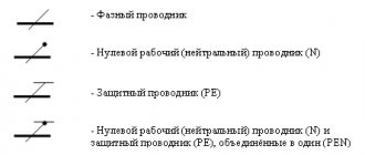
Symbols for reading circuit diagrams
Circuit diagram symbols resemble basic ones.
To learn how to read them, you should remember the standard icons of all elements found in electrical devices. The main ones are: designations of letters and numbers, dotted, mechanical and shielded lines, coaxial cables and others. In this list, you can omit icons for radio devices, since when drawing up a diagram of the electrical network of a residential building, they are not so in demand. Examples of notation:
- detachable elements are indicated by the icons X1 and X2;
- Common symbols for resistors are R1 (variable resistor), SA1 (switch). Since the elements are connected, a dotted line is drawn between them.
- shielding is drawn with a dash-dot line, connecting it to the common wire. This designation is necessary since many components of electrical devices react to a magnetic field.
In order to correctly read circuit diagrams, you need to learn to distinguish the circuits of the main circuit from the secondary ones. The main circuits are based on parts that convert the flow of electricity, and the secondary circuits are based on components with a power of no more than 1 kilowatt. They take into account and measure electricity consumption and coordinate the operation of electrical appliances.
Sources
- https://www.asutpp.ru/uslovnye-oboznachenija-v-jelektricheskih-shemah.html
- https://electro-znatok.ru/stati/elektricheskie-oboznacheniya-na-shemah/
- https://stroychik.ru/elektrika/uslovnye-oboznacheniya-na-shemah
- https://rusenergetics.ru/oborudovanie/uslovnye-oboznacheniya-v-elektricheskikh-skhemakh
- https://remboo.ru/inzhenernye-seti/elektrika/oboznacheniya-na-elektricheskih-shemah.html
- https://www.bazaznaniyst.ru/oboznachenia-v-elektricheskix-chemah/
Jan 25, 2021
What are the different grounding schemes?
Progress does not stand still. And along with the development of digital technologies, all other aspects of our lives are improving. This also affected grounding, which now has several options for its circuits. In this article we will tell you about what basic grounding schemes exist, and in what cases their use would be appropriate.
Varieties
According to international agreement, grounding circuits are designated in large Latin letters. The first one shows the grounding of the power source, the second - the open parts of a certain electrical installation.
So, in accordance with this, we can distinguish the following systems:
From this abbreviation: T – grounding, N – grounding, I – insulation
Next we will look at each of them.
Systems TN-C, TN-CS and TN-S
The TN-C circuit involves combining the protective and working conductors. Its biggest drawback will be the inoperability of RCD systems. We will not dwell on it in detail, since now it is already considered the least reliable, and is practically not used anywhere.
At one time it was replaced by a more reliable and complex TN-S circuit. The grounding and grounding conductors run separately in it. Its undeniable advantages include:
- There is no need to follow the contour;
- The most secure of all existing ones;
- Additional devices can be used to improve security.
However, along with reliability, it is the most expensive of all, and its equipment is associated with certain difficulties.
The TN-CS system is considered a compromise between cost and reliability. In it, the working conductor (grounding) is combined with grounding on the path from the house to the substation, and in the building these two wires are laid separately (something in between the previous two).
This is the most common scheme for residential buildings and urban buildings. Among its advantages are the following:
- Increased reliability, since all two wires will be laid in the house;
- Low cost;
- Widespread.
But it is worth mentioning that there is a possibility of the wire from the substation burning out, which can result in high phase voltage. To prevent this, a number of special measures must be taken.
TT and IT systems
Until recently, TT was not allowed in the country, but is now used for mobile structures, such as kiosks and stalls. It requires reliable pin grounding, and for greater safety, RCD system equipment. The neutral in this system goes deep into the ground, and the open leading elements are connected directly to the circuit.
In an IT circuit, the neutral is isolated from ground and the exposed elements are grounded. It is used in medical institutions and laboratories where people’s work involves sensitive equipment.
Thus, considering various systems, we found out that the most common is TN-CS, which is not as expensive as TN-S, but is still more reliable than TN-C.
Dimensions
According to the requirements of GOST 21130-75, the parameters of the symbol image differ depending on the method of its application to the body of the electrical installation. For example, the minimum diameter of a sign made by casting or stamping is 10 mm, and for one made by impact, this parameter will be 14 mm. One of the most commonly used dimensions of the ground safety sign is 30 x 30 mm. More details on the dimensions of the grounding symbol can be found in clause 3.1 of the above GOST.
Design and dimensions of grounding signs made by casting in metal (including non-ferrous) and pressing into plastic class=”aligncenter” width=”768″ height=”370″ Dimensions of grounding signs made by casting methods
Design and dimensions of grounding signs made by impact
Dimensions of grounding signs made by impact
The best way to update your business signs is to purchase stickers. The grounding sign on stickers can be in vector format or in the form of a picture. The stickers have a service life of up to 2 years, and replacing them is easy. You can also download a grounding sign stencil and apply the symbols with paint. When designing a grounding loop and installing new equipment, it is better to check in advance for the presence of “Grounded” icons on their housings.
source
How does a ground wire work?
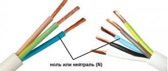
Many people often wonder how a ground wire works. For example, if the slightest malfunction occurs during the operation of household appliances, this may be due to damage to the phase cable or the occurrence of an electric current leak. As for residents of the private sector, these areas are mainly electrified by installing overhead power lines. As a rule, these are two-wire lines that consist of phase and neutral wires.
You may be interested in: Laying electrical wiring in a wooden house
Checking the functionality of the ground loop
Important! Gusts of wind, falling branches and precipitation can break the power cable at any time, and if the building does not have a protection system in the form of grounding and an RCD device, then not only the owner of the house, but also his household appliances may suffer.
I don't meet people at the club
How to distinguish wires by color and markings - Domostroy - postnamante.tk
The concept of phase and zero, the color of the wires phase, zero, ground. It becomes reasonable to ask what color the phase and zero in are indicated by. red and a “+” sign, and the negative conductor is blue with a “-“ sign. the earth is yellow-green as a rule - BLUE, RED, according to the first, according to the second BROWN, the earth has always been yellow-green. The grounding sign, applied to the body of electrical equipment, represents a general graphic designation of the connection of a section of the circuit to the “ground”.
First of all, these are the places where the protective conductors are connected to the main grounding buses, near the terminals or studs for connecting the protective conductor. Friends, let's figure out where grounding signs are installed in electrical installations, according to the rules and GOST. The next regulatory document is GOST. By the way, the same paragraph says that the place for connecting the grounding conductor must be cleaned of corrosion, and the sleeve to be connected must not have surface paint.
Regarding cleaning from corrosion, I think this is a very important note. I personally spent a long time looking for where this action is written.
And of course, let’s not forget about our native PUE. Grounding sign dimensions according to GOST Friends, we have found out that the places where equipment is connected to the grounding conductor must be marked with a special symbol. The dimensions of this symbol and the methods for its implementation are regulated by GOST. This GOST deals with the application of signs on equipment by the manufacturer.
There are not many execution methods in this case: As you can understand, signs applied in this way will have either a depressed or convex surface. After manufacturing using one of the above methods, the sign is additionally painted for greater clarity.
Designation L and N in electrics
Every time you try to connect a chandelier or sconce, a light or motion sensor, a hob or exhaust fan, a heated floor thermostat or an LED strip power supply, as well as any other electrical equipment, you can see the following markings near the connection terminals - L and N.
Let's figure out what the designations L and N mean in electrical engineering.
As you probably guessed, these are not just arbitrary symbols, each of them carries a specific meaning and serves as a hint for correctly connecting the electrical appliance to the network.
Turning the letter "o" into a degree icon in Word
In Word, which is quite often used for typing text on a computer, you can turn a small (lowercase) letter “o” into a “degree (Celsius)” symbol. The letter "o" can be Russian or English - it doesn't matter. The main thing is that it is small.
First, let’s write down the expression “plus 15 degrees Celsius” so that the letter “o” is in place of the “degree Celsius” icon on the table. That is, let’s enter the following text in the Word editor: +15оС. It is clear that this text only vaguely resembles what should actually be written down. After all, the letter “o” is in no way similar to the “degree” icon, except that it is as round as this icon.
To turn the letter “o” into a degree symbol, just make it superscript in Word. To do this, select the letter “o” in the entered expression +15оС, as shown by number 1 in Fig. 1:
Rice. 1 (Click to enlarge). Procedure in Microsoft Word to turn the letter "o" into a "degree" icon.
Then, in the top menu of the Word editor, find the “Font” option (2 in Fig. 1) and left-click on the inclined arrow to the right of the “Font” inscription to open the “Font” menu. In the “font” menu that opens, find a place to check the box next to the “Superscript” option (3 in Fig. 1).
Now all that remains is to click on the “OK” button (4 in Fig. 1). And in the end you will get the required expression with the “degree” icon familiar to the eye (Fig. 2):
Rice. 2. The result of performing the actions to transform the letter “o” into the “degree” icon in Word.
It may happen that the characters in the expression with “degrees” will have different sizes, and together they will look ugly. For example, it might look like this:
In the example shown, the “degree” icon “falls out” too high. This may be because the characters in the expression were entered using different fonts. Then you need to select the entire expression obtained by converting the letter “o” into “degree”. After this, you need to select a single font for the entire selected expression. Then everything will fall into place, it should look like this:
Common wire and grounding in circuits
Before you understand where and how grounding points and the common wire are depicted, you need to understand what they are. According to the definition, the common wire (ground, body) denotes the point at which the electric potential is taken to be zero. According to this, all other values in the circuit are measured relative to this point, called the common wire.
As a rule, the common wire in circuits is the one against which all circuit voltages are measured. In electronic circuits, this function is not always carried by the negative pole. There are many circuits in which this function is assigned to the positive wire, while for circuits that have bipolar power supply (that is, power supply via the +-Upit system), the common wire is the common point of the power sources.
In other words, the common wire of a circuit can be called the conductor to which the largest number of terminals of the entire circuit converge. This concept was precisely introduced in order to simplify the process of drawing and reading circuits (after all, instead of laying conductors to it, a sign consisting of a vertical line going into the middle of a horizontal line is often simply drawn), at the same time this allows you to save space on the circuit drawing.
In relation to small-sized electronic circuits, which are made on boards using printed wiring, the common wire (also known as grounding) is made in the form of a copper substrate. In addition, conductors for this purpose on printed circuit boards, as a rule, have a fairly large area (much larger than that of other conductors). In relation to any electrical (or electronic) circuit, the common wire (aka ground) is such a convenient thing that reading any circuits if they do not have this element is significantly difficult and inconvenient.
For circuits intended to operate at high speeds, it has long been axiomatic that every square millimeter of the board that does not have electronic components or conductors should be filled with a polygon intended for a ground wire. If this is not done, the result can be very disastrous. However, there are cases in which it is quite difficult (and sometimes impossible) to follow these rules (for example, when the installation is quite dense). To overcome this complexity, it is necessary to reduce the installation density, thereby allocating more space for the “common wire”. An example of maximum filling of a grounding (ground) polygon can easily be any industrial-type printed circuit board (for example, the “signet” of any tape recorder or TV). If you need to find the common wire on such boards, then by poking at the conductor with the largest area, we will get to the common wire.
1.7.68
Fences and shells in electrical installations with voltages up to 1 kV must have a degree of protection of at least IP 2X, except in cases where large clearances are necessary for the normal operation of electrical equipment.
Guards and shells must be securely fastened and have sufficient mechanical strength.
Entering the fence or opening the shell should be possible only with the help of a special key or tool, or after removing the voltage from live parts. If these conditions cannot be met, intermediate barriers with a degree of protection of at least IP 2X must be installed, the removal of which must also be possible only with the help of a special key or tool.
Letter designations of the grounding system
Letter designations of the grounding system
It will be easier to understand and remember the designation of the type of grounding system if you know what the Latin letters of the type of grounding system mean. For ease of memorization, you can choose the most convenient foreign words, the first letters of which indicate: T (terra - earth); N (neutral - neutral); I (isolate – isolated);
S (separated, selective – separated); C (complete - general, combined - combined);
PE (protecte eath, protective earthing – protective earth); PEN (protective earthing, neutral - protective earth and neutral).
The first letter in the designation indicates the state of the neutral (as connected to the ground) of the power source (transformer, generator, and sometimes a UPS, inverter, stabilizer, etc., if they change the state of the neutral and the consumer is turned on after them) relative to the ground. Characterizes the connection to the ground of the current-carrying conductors of the source. T - grounded neutral, direct connection of one point of the current-carrying parts of the power source to the ground; I - isolated neutral, all current-carrying parts are isolated from ground, or one point is grounded through high resistance.
The second letter characterizes the connection to the ground of open conductive parts of the equipment (OFC or housing) and third-party conductive parts (HFC). Describes the connection to the ground of the consumer (equipment frame).
T - direct connection of the power supply with the ground (regardless of the nature of the connection of the power source with the ground); N - direct connection of the frequency converter with the grounding point of the power source (in AC systems it is usually grounded by neutral); I - OFC (housing) is not connected to ground or neutral.
The following letters are the combination in one conductor or the separation of the functions of the zero working and zero protective conductors:
S - the function of the zero protective and zero working conductor is provided by separate conductors; C - the functions of the neutral protective and neutral working conductors are combined in one conductor (PEN conductor).
TT - the source neutral is solidly grounded (outside the consumer network), electrical equipment housings are directly connected to the ground, regardless of the grounding of the source neutral; IT - there is no direct connection of the neutral to the ground; connection to the ground through a resistance, air gap, arrester, etc. is allowed. Direct connection to the ground of the consumer's conductive parts, independent of network grounding.
TN - the neutral of the source is solidly grounded, the electrical equipment housings are connected to the neutral wire (PE or PEN conductor); TN - C - the functions of the zero working and zero protective conductors are combined in one conductor throughout the network; TN - S - zero working and zero protective conductors operate separately throughout the system; TN - C - S - the functions of the zero working and zero protective conductors are combined in one conductor in the part (beginning) of the network;
TI - source neutral is solidly grounded (outside the consumer’s network), there are no connections to the ground and to the network grounding of the consumer’s conductive parts, not in the standards or GOST
L (line conductor) - linear (phase) conductor; LE - grounded linear conductor (having an electrical connection to the local ground); PEL conductor or combined protective grounding and linear conductor (conductor performing the functions of protective grounding and linear/phase conductors). For example, you can ground the connection point of the windings (delta), or one of the terminals of a single-phase generator, or one of the terminals of a two-wire DC system; M-conductor or mid-conductor (a conductor electrically connected to the energized middle portion of a DC electrical system and used to transmit electrical energy); PEM conductor or a combined protective grounding and middle conductor (a conductor that performs the functions of a protective grounding and middle conductor).
FE is a functional grounding conductor; it is a grounding conductor in an electrical installation up to 1 kV, serving for functional grounding. Functional grounding is grounding that ensures the normal functioning of the device, on the body of which, at the request of the designer, there should not be even the slightest electrical potential (sometimes this requires the presence of a separate electrically independent grounding conductor).
PEF conductor is a combined protective and functional grounding conductor. This is a conductor in an electrical installation up to 1 kV, combining the functions of a protective and functional grounding conductor.
Main ground bus
What should be used as the main grounding bus inside the input device?
Answer. A PE bus should be used.
What are the requirements for the main grounding bus? Answer. Its cross-section must be no less than the cross-section of PE (PEN) - the conductor of the supply line. It should, as a rule, be copper. It can be used in steel. The use of aluminum tires is not permitted.
What are the requirements for installing the main grounding bus? Answer. In places accessible only to qualified personnel, for example, switchboard rooms of residential buildings, it should be installed openly. In places accessible to unauthorized persons, for example, entrances and basements of houses, it must have a protective shell - a cabinet or drawer with a door that can be locked with a key. There must be a sign on the door or wall above the tire.
How should the main grounding conductor be installed if the building has several separate inputs? Answer. Must be completed for each input device.
What letter and color indicate zero and phase in electrical engineering?
When independently connecting electrical equipment - lamps, ventilation, automatic machines, users can find the letter designations of the terminals. L, N in electrics are the phase and ground to which the corresponding cables are routed.
- Letter marking of wires
- Conductor insulation coating colors
- Why use color coding
- The nuances of manual color marking
- Wiring colors as a way to speed up installation
- Requirements for wiring colors during installation
Letter marking of wires
For household and industrial power lines, insulated wires with internal conductors are used. Products differ depending on the color of the insulating coating and markings. The designation of phase and zero in electrics speeds up repair and installation work.
Marking of cables in electrical installations under voltage up to 1000 V is regulated by GOST R 50462-2009:
- in clause 6. 2.1 it is indicated that the neutral conductor is marked as N;
- clause 6.2.2. states that the protection wire with grounding is designated PE;
- in paragraph 6.2.12 it is said that in electrics L is a phase.
Understanding the markings simplifies installation work in commercial, residential and administrative buildings.
L – phase designation
In an AC network, there is a live phase wire. Translated from English, the word Line means an active conductor, line, and is therefore marked with the letter L. Phase conductors must be covered with colored insulation, since, being exposed, they can cause burns, human injuries, fire or failure of various equipment.
N – alphabetic symbol of zero
The sign of a neutral or neutral working cable is N, from the abbreviation of the terms neutral or NULL. When drawing up a diagram, the zero switching terminals in a single-phase or three-phase network are marked this way.
The word “zero” is used only in the CIS countries; throughout the world the core is called neutral.
PE – grounding index
If the wiring is grounded, the letter marker PE is used. In English, the meaning of Protective Earthing is translated as grounding wire. Clamps and contacts for switching with ground zero will be designated similarly.
Conductor insulation coating colors
It is necessary to color-code grounding, phase and neutral cables in accordance with the requirements of the PUE. The document establishes color differences for grounding in the electrical panel, as well as for zero and phase. Understanding the insulation color code eliminates the need to decipher letter markers.
Ground wire color
In the Russian Federation, the European standard IEC 60446:2007 has been in force since January 1, 2011.
It notes that the grounding has only yellow-green insulation. If an electrical circuit is drawn up, the ground should be designated as PE. There is a grounding core only in cables with 3 cores.
PEN conductors used in old buildings combine ground and neutral conductors. The insulating coating in this case has a blue grounding color and yellow-green cambrics at the connection points and ends of the wire. In some cases, the reverse marking was used - yellow-green color zeroing with blue tips.
The ground and neutral conductors of PEN cables are thinner than the phase conductors.
The organization of protective grounding is a prerequisite for creating an electrical network in residential and industrial buildings. Its necessity is indicated in the PUE and GOST 18714-81. Standards state that zero grounding should have the lowest resistance. To avoid confusion, use color markings for the cables.
Color designation of zero working contacts
In order not to confuse where the phase is and where the zero is, instead of the letters L and N, they are guided by the colors of the cables. Electrical standards note that the neutral is blue, light blue, blue-white, regardless of the number of wires.
Zero can be designated by the Latin letter N, which is read as a minus in the diagram. The reason for reading is the participation of zero in the closure of the electrical circuit.
Phase wire colors
A phase is a live line that, if touched carelessly, can lead to electric shock. Novice craftsmen often have difficulty finding a cable. The phase is indicated by black, brown, cream, red, orange, pink, purple, gray and white.
The alpha phase index is L. It is used where the wires are not color coded. When connecting a cable to several phases, a serial number or Latin letters A, B, C are placed next to the letter L. The phase is also often marked as plus.
The phase wire cannot be blue, cyan, green or yellow.
Why use color coding
You can determine L and N in electrics using an indicator screwdriver. You will need to touch the tip to the part of the product without an insulating coating. The indicator glow indicates the presence of a phase. If the LED does not light up, the wire is zero.
Color coding reduces the time spent searching for the right wire and troubleshooting. Knowing the colors of conductors also eliminates the risk of electric shock.
The nuances of manual color marking
Manual marking is used when using wires of the same color in old buildings. Before starting work, a diagram with the color values of the conductors is drawn up. During the installation process, you can mark current-carrying conductors:
- standard cambrics;
- cambrics with heat shrinkage;
- insulating tape.
The rules allow the use of special marking kits. The installation points for markers to indicate zero and phase are indicated in the PUE and GOST. These are the ends of the wire and where it connects to the bus.
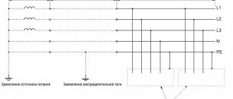
TN: grounding system with solidly grounded neutral
In this system, protection is carried out by connecting a solidly grounded neutral to non-insulated components of the electrical installation. In the TN grounding system, the conductor is PE, that is, the “zero” conductor. That is, when arranging it, housing screens and parts of electrical consumers that conduct current must be connected to a common “zero” - a conductor that is connected to the neutral.
The functional “zero” in this case is designated by the letter “N”, and the combination of the “zero” functional and protective conductor is “PEN”. This grounding system has three subtypes TN-CS, TN-C and TN-S. The differences between them lie in the different ways of connecting the “PE” and “N” conductors.
This system does not use the method of neutral grounding using an arc suppression reactor, which in other types of systems is used as a compensating device.
Designation N in electrical
“N” is a marking formed from the first letter of the word Neutral (neutral) - the generally accepted name for the neutral working conductor, in Russia more often called simply the neutral conductor or briefly Zero (Zero). In this regard, the English word NULL (zero) is well suited, you can focus on it.
the designation N marks clamps and contact connections for connecting the neutral working conductor/neutral wire. Moreover, this rule applies to both single-phase and three-phase networks.
The colors of the wire that mark the neutral wire (zero, zero, zero working conductor) are strictly blue (light blue) or white-blue (white-blue).
Graphic symbols in electrical diagrams
Regarding graphic symbols in electrical circuits, GOST 2.702-2011 refers to three other GOSTs:
- GOST 2.709-89 “ESKD. Conventional designations of wires and contact connections of electrical elements, equipment and sections of circuits in electrical circuits.”
- GOST 2.721-74 “ESKD. Conditional graphic designations in schemes. Designations for general use"
- GOST 2.755-87 “ESKD. Conventional graphic symbols in electrical diagrams. Switching and contact connection devices."
Conventional graphic symbols (UGO) of automatic circuit breakers, switches, contactors, thermal relays and other switching equipment that is used in single-line diagrams of electrical panels are defined in GOST 2.755-87.
However, there is no designation for RCDs and difavtomats in GOST. I think it will soon be reissued and the RCD designation will be added. In the meantime, each designer depicts an RCD according to his own taste, especially since GOST 2.702-2011 provides for this. It is enough to provide the UGO designation and its explanation in the explanations of the diagram.
In addition to GOST 2.755-87, to complete the circuit, you will need to use images from GOST 2.721-74 (mainly for secondary circuits).
All designations of switching devices are based on four basic images:
using nine functional features:
| Name | Image |
| 1. Contactor function | |
| 2. Switch function | |
| 3.Disconnector function | |
| 4. Switch-disconnector function | |
| 5. Automatic triggering | |
| 6. Travel or limit switch function | |
| 7. Self-return | |
| 8. No self-return | |
| 9. Arc suppression | |
| Note: The designations given in paragraphs. 1 - 4, 7 - 9, are placed on fixed contacts, and the designations in paragraphs. 5 and 6 - on moving contacts. |
Basic graphic symbols used in single-line diagrams of electrical panels:
| Name | Image |
| Circuit breaker (automatic) | |
| Load switch (switch) | |
| Contactor contact | |
| Thermal relay | |
| RCD | |
| Differential automatic | |
| Fuse | |
| Automatic switch for motor protection (circuit breaker with built-in thermal relay) | |
| Load switch with fuse (switch with fuse) | |
| Current transformer | |
| Voltage transformer | |
| Electric energy meter | |
| A frequency converter | |
| Normally closed contact of a push-button switch without self-reset with the control element opening and returning automatically | |
| Normally closed contact of a push-button switch without self-reset with opening and return of the control element by pressing the button a second time | |
| Normally closed contact of a push-button switch without self-reset with opening and return of the control element by pulling the button | |
| Normally closed contact of a push-button switch without self-reset with opening and returning of the control element via a separate drive (for example, pressing a reset button) | |
| Normally closed contact with delay when activated | |
| Normally closed contact with delay during return | |
| Normally closed contact with delay during operation and return | |
| Normally closed contact with delay when activated | |
| Normally closed contact with delay during return | |
| Normally closed contact with delay during operation and return | |
| Contactor coil, general designation for relay coil | |
| Impulse relay coil | |
| Photo relay coil | |
| Timing relay coil | |
| Motor drive | |
| Lighting lamp, light indication (light bulb) | |
| A heating element | |
| Plug connection (socket): socket pin | |
| Arrester | |
| Surge suppressor (SPD), varistor | |
| Dismountable connection (terminal) | |
| Ammeter | |
| Voltmeter | |
| Wattmeter | |
| Frequency meter |
The designations of wires and busbars in electrical panels are determined by GOST 2.721-74.
| Name | Image |
| Electrical communication line, wires, cables, buses, group communication line | |
| The protective conductor (PE) may be shown as a dashed line | |
| Graphic branching (merging) of group communication lines | |
| Crossing of electrical communication lines, group communication lines of electrically not connected wires, cables, tires, not electrically connected | |
| Electrical communication line with one branch | |
| Electrical communication line with two branches | |
| Bus (if it is necessary to graphically separate electrical communication lines from the image) | |
| Branch bus | |
| Buses graphically intersecting and not electrically connected | |
| Branches (tap-offs) from the bus |
Designation L in electrical
“ L ” - This marking came to electrical engineering from the English language, and it is formed from the first letter of the word “Line” (line) - the generally accepted name for a phase wire. Also, if it is more convenient for you, you can focus on such concepts of English words as Lead (lead wire, core) or Live (under voltage).
Accordingly, the designation L marks the clamps and contact connections intended for connecting the phase wire. In a three-phase network, alphanumeric identification (marking) of phase conductors “L1”, “L2” and “L3”.
According to modern standards (GOST R 50462-2009 (IEC 60446:2007)) in force in Russia, the colors of phase wires are brown or black. But often, white, pink, gray or a wire of any other color except blue, white-blue can be found , blue, white-blue or yellow-green.
Grounding sign: designation on diagrams
Correct and high-quality connection of electrical device housings with a grounding loop (or device, charger) plays an important role in the safety aspect of using electrical equipment. In order to know whether the device is connected to ground, a special symbol is applied to it.
Places for marking
The main tasks of the grounding symbol include an information function. The size of the marking is proportional to the size of the equipment.
The grounding sign can often be seen on electronics and household appliances; it is usually applied to the case, but first of all it is used to mark the connection points between the device and the charger, i.e. at the points where the protective conductors are connected to the grounding buses, near the connection point of the grounding conductor, on the terminals and next to them, etc.
Marking methods
There are several ways to apply such symbolism:
- stamping,
- metal casting,
- impact method,
- pressing in plastic.
But not all elements and devices can be marked in this way. However, regulatory documents do not prohibit applying special symbols in other ways, for example, applique, paint, etc. Therefore, applying a designation using a sticker with the desired symbol has become quite common
In this case, the main attention should be paid to the size of the sign - it must strictly comply with the standards specified in the PUE and GOST 21130-75
Picture on electrical diagrams
It is also necessary to indicate grounding elements on electrical circuit drawings. This is established by GOST 2.721-74, as well as the Unified System of Design Documentation. If the symbol on the case must be uniform and can differ only in size, then several types of symbols are provided for circuits.
- General designation for connecting a circuit to ground. Often used in electronic and electrical circuits as a working or measuring ground.
- Silent. This is a rare type, but it is required for marking a device with its own grounding electrode among many devices connected to common memory devices.
- Protective. This is the most common designation, similar to what is applied to equipment housings. This grounding sign marks connections between live parts and the ground.
- Connection of the current-carrying part to the device. It does not have a full grounding effect.
Grounding signs play an important informational role, and in order to indicate the presence and location of grounding on equipment, they must be used in accordance with the dimensions determined by government regulations.
Grounding Designation
If we are talking about the designations L and N in electrical engineering, we cannot help but note this sign - , which can also almost always be seen together with these two markings. This icon marks clamps, terminals or contact connections for connecting a protective grounding wire ( PE - Protective Earthing), also known as a neutral protective conductor, grounding, earth.
Unfortunately, often the electrical wiring in our apartments and houses is not carried out in compliance with all strict standards and rules for color and alphanumeric markings for electricians. And knowing the purpose of the L and N markings on electrical equipment is sometimes not enough for proper connection. Therefore, be sure to read our article “How to determine phase, zero and grounding yourself, using improvised means?” If you have any doubts, this material will come in handy.
UGO dimensions
Dimensions of graphic symbols in electrical diagrams
| Name | Designation | Name | Designation |
| Switching device contact. General designation: closing | Switching device contact. General designation: switching | ||
| Heating element | Contact without self-resetting: normally open | ||
| Push-button switch | Normal contact with retarder, active: when activated | ||
| Plug connection contact: pin | Plug connection contact: socket | ||
| Removable connection contact | Electric machine rotor | ||
| Sensing part of electrothermal relay | Electromechanical device coil | ||
| Incandescent lamp (lighting and signal) | Electric bell | ||
| The fuse is fusible. General designation | Resistor is constant | ||
| Galvanic or battery cell | Grounding | ||
| Fixed capacitor | Electrolytic capacitor |
GOST 2.721-74
| Name | Designation | Name | Designation |
| Drive using bimetal | Float drive | ||
| Drive driven by pressing a button | Diaphragm drive |
GOST 2.755-87
The dimensions of the graphic symbols are given in the modular grid.
| Name | Designation | Name | Designation |
| Switching device contact 1) normally open | Switching device contact 2) normally open | ||
| Switching device contact 3) changeover | Pulse closing contact during operation and return |
| Name | Designation | Name | Designation |
| Three-pole switch | Electric machine stator | ||
| Inductor, winding | Electro-mechanical device coil: with one additional graphic field | ||
| Electrical measuring device: integrating (for example, an electric energy meter) | Electrothermal device without heating chamber; electric heater |
GOST 2.730-73 (amended 1989)
Dimensions (in modular grid) of symbols
| Name | Designation | Name | Designation |
| Diode | Thyristor diode | ||
| Transistor | Field effect transistor |
Grounding
Disclaimer: This article is for informational purposes only and is not intended to be a normative document. When performing work related to electricity, you should be guided by the Electrical Installation Rules (PUE).
Definitions
Grounding is the deliberate connection of non-current-carrying elements of equipment, which may become energized as a result of an insulation breakdown, to the ground.
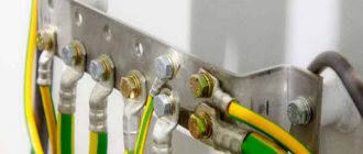
Grounding consists of a ground electrode (a conductive part or a set of interconnected conductive parts that are in electrical contact with the ground directly or through an intermediate conducting medium) and a grounding conductor connecting the grounded device to the ground electrode. The ground electrode can be a simple metal rod (most often steel, less often copper) or a complex set of specially shaped elements. The quality of grounding is determined by the value of the electrical resistance of the grounding circuit, which can be reduced by increasing the contact area or the conductivity of the medium - using many rods, increasing the salt content in the ground, etc. As a rule, the electrical grounding resistance is standardized. Main ground terminal. To minimize electromagnetic interference and ensure electrical safety, grounding should be done with a minimum number of closed loops. Ensuring this condition is possible by performing the so-called main ground clamp (MGZ), or bus. The main ground terminal should be located as close as possible to the input power and communications cables and connected to the grounding terminal(s) with the shortest possible length of conductor.
This arrangement of the ground protection zone ensures the best equalization of potentials and limits the induced voltage from industrial interference, lightning and switching overvoltages coming from outside through communication cable screens, power cable armor, pipelines and antenna inputs. The following must be connected to the GZZ (bus):
- grounding conductors;
- protective conductors;
- conductors of the main potential equalization system;
- working grounding conductors (if necessary).
Protective and working (technological, logical, etc.) grounding conductors, lightning protection grounding conductors, etc. must be connected to the main grounding terminal (bus). The rules and requirements for the installation of the GZZ are set out in detail in the PUE.
An exposed conductive part is a conductive part of an electrical installation that is accessible to touch, not normally energized, but which may become energized if the main insulation is damaged. Exposed conductive parts include metal housings of electrical equipment.
Current-carrying part is an electrically conductive part of an electrical installation that is under operating voltage during its operation.
Indirect touch is electrical contact of people and animals with exposed conductive parts that become energized when the insulation is damaged. That is, this is touching the metal casing of electrical equipment when the insulation on the casing breaks down.
Designations
Protective grounding conductors in all electrical installations, as well as neutral protective conductors in electrical installations with voltages up to 1 kV with a solidly grounded neutral, including busbars, must have the letter designation PE and a color designation with alternating longitudinal or transverse stripes of the same width (for busbars from 15 to 100 mm ) yellow and green colors. Zero working (neutral) conductors are designated by the letter N and the color blue. Combined neutral protective and neutral working conductors must have the letter designation PEN and a color designation: blue along the entire length and yellow-green stripes at the ends.[1]
Graphic symbols used to indicate conductors on diagrams:
Letter designations of the grounding system
The first letter in the designation of the grounding system determines the nature of the grounding of the power source:
T – direct connection of the neutral of the power source to the ground; I – all live parts are isolated from the ground.
The second letter determines the nature of grounding of exposed conductive parts of the building's electrical installation:
T – direct connection of the open conductive parts of the electrical installation of the building with the ground, regardless of the nature of the connection of the power source with the ground; N – direct connection of open conductive parts of the building’s electrical installation with the grounding point of the power source.
The letters following N through a dash determine the nature of this connection - the functional method of constructing the zero protective and zero working conductors:
S – the functions of zero protective PE and zero working N conductors are provided by separate conductors; C – the functions of the neutral protective and neutral working conductors are provided by one common conductor PEN.
Errors in the grounding device
Incorrect division of the PEN conductor The following method of “creating” a PE conductor is extremely dangerous: the working neutral conductor is determined directly in the socket and a jumper is placed between it and the PE contact of the socket. Thus, the PE conductor of the load connected to this socket is connected to the working zero.
The danger of this scheme is that a phase potential will appear on the grounding contact of the socket, and, consequently, on the body of the connected device, if any of the following conditions are met:
Protective function of earthing
Principle of protective action
The protective effect of grounding is based on two principles:
Thus, grounding is most effective only in combination with the use of an RCD. In this case, with most insulation failures, the potential on grounded objects will not exceed dangerous values. Moreover, the faulty section of the network will be disconnected within a very short time (tenths to hundredths of a second - the response time of the RCD).
Grounding operation in case of electrical equipment faults
A typical case of electrical equipment malfunction is the contact of phase voltage with the metal body of the device due to insulation failure[4]. It should be noted that modern electrical appliances that have a pulsed secondary power supply and are equipped with a three-pole plug (such as a PC system unit), in the absence of grounding, have a dangerous potential on the case, even when they are fully operational.[5]
Self-production
Making your own grounding is a sequential process consisting of several stages, each of which has its own characteristics. This does not require a pile of papers, since permission is not required in private construction. Installation should be carried out in the warm season, when the soil has thawed, dried out and settled.
To work you will need:
- welding machine;
- grinder, hammer drill;
- level, tape measure;
- pliers;
- shovel, sledgehammer;
- brush, paint;
- corrugated tube;
- aluminum tape.
The work is performed in the following sequence:
- Drawing up a project. Based on it, calculations of materials and equipment are carried out. You should make a small reserve, as errors are possible during the work process.
- Carrying out markings. The turf layer is carefully removed, then a pit of a given shape is torn off. The excavated material must be preserved, as it will be used for backfilling.
- From the middle of one side or from the corner, a flat trench is dug towards the building. It is needed for laying a cable or other current conductor between the frame and the electrical panel.
- The electrodes are cut out. Their ends are pointed for easier immersion into the soil. After this, the pins are driven into the ground at the corners of the trench. If a corner is used, holes are pre-drilled and the openings are filled with a mixture of earth and salt.
- The sides of the contour are cut out. They are connected to the electrodes and to each other. Welding areas are painted over.
- Near the ditch to the house, a bolt is welded to the frame. The cable is screwed to it. The joint is closed with a plastic bottle, the neck of which is sealed with aluminum tape.
- Entry into the house is made in the basement. To prevent chafing of the cable insulation, a flexible steel tube is inserted into the hole. The cable is pulled into it and connected to the shield.
- The final stage is filling the ditches with soil, leveling it and compacting it.
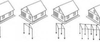
Grounding: types, diagrams
Grounding
– connection of conductive elements of industrial or household equipment with the ground or common wire of the electrical system, against which the electrical potential is measured. Ignoring this measure or its incorrect implementation causes long-term downtime and failure of expensive equipment, high measurement errors, slowdown in the functioning of various systems, and accidents.
The grounding scheme is determined by the functional purpose.
The content of the article
- Types of grounding
- Typical grounding errors
- Grounding symbols on the diagram
Types of grounding
Protective
Required to protect a person from electric shock. To do this, the conductive elements of the equipment are connected to the ground by a grounding device, which includes: a conductor that is in contact with the ground (grounding conductor) and grounding conductors. The grounding circuit can be arranged using natural or artificial grounding conductors. Natural ones include steel and reinforced concrete frames of industrial buildings, reinforced concrete foundations, steel permanently laid pipelines, aluminum cable sheaths. Artificial grounding conductors are made from pipes, angles, and rods.
location, dimensions and designation on diagrams
All distribution boards and other types of modular electrical equipment have a grounding sign on the housing. Using this designation, the junction of the main part of the body of the selected electrical equipment with the grounding elements is marked. Thanks to the grounding cable, safety is ensured when using electrical equipment in industrial production.
Location on the equipment
Depending on the type of electrical equipment, GOST standardizes the marking option and the place on the housing where the connection to ground should be indicated:
- Grounding symbol near the clamp/clip on the shield. According to paragraph 6.4.6 of GOST R 51778 of 2001, the designation must be located at the clamp. Additionally, a sign marks the place where the neutral protective conductor PE is connected.
- “Grounded” sign next to the connection between the metal parts of the housing and the PE conductor. The option is due to the requirements of safety rules 08-624-03. A sticker can be glued to the case or the corresponding symbol can be engraved directly into the metal.
Important! The grounding sign is applied to the surface of the electrical panel in any indelible way. The junction of the grounding cable and the shield itself is cleaned of corrosion, and some of the paint is removed from the connected area
Options for marking electrical equipment
Most often, a symbol or letter designation is applied to the shields or control panels directly at the manufacturer. The designation location has a convex or depressed relief surface. On new production lines, the “grounded” sign on the shields is cast directly during the manufacture of the metal or plastic housing.
Regardless of whether there is an embossed marking or not, the ground symbol is additionally colored for visual highlighting on the surface of the housing.
For old electrical appliances, production usually simply uses a grounding sign sticker, which is glued to a special adhesive compound or using adhesive tape. As a result, it is possible to quickly mark all the panels and significantly save money. It is worth noting that the use of a grounding symbol in the form of a sticker does not contradict the current GOST.
How is grounding indicated in diagrams and drawings?
When designing electrical circuits on a production line, not only structural elements, switching devices and control equipment are marked, but also the location of the ground loop.
The regulatory document, which specifies all the features of the sign designation on the diagrams, is GOST 2.721 of 1974. Designation of a silent and protective version of grounding signs in the drawings
Important! To select the correct symbol, special attention must be paid to the characteristics of the equipment to be grounded. Depending on the type of grounding, in addition to the icon, alphabetic symbols are added (N, PE, PEN)
Dimensions of the grounding sign according to GOST 21130-75
The specified GOST specifies not only the dimensions, but also the methods of applying the sign on the equipment of the manufacturer of panels and other electrical equipment. 4 types of designation are regulated:
- Stamping method.
- Casting in steel case.
- Impact method.
- Pressing method in plastic cases.
Clause 3.1 of the above GOST specifies the possibility of making signs using appliqué, paint, or photochemical methods. The only strict requirement is their size:
When casting or pressing on the body
Hh2D*bhr
| 5 | 3,6 | 10 | 0,7 | 2,5 | 0,35 |
| 8 | 6,0 | 16 | 1,2 | 4,0 | 0,6 |
| 10 | 7,0 | 20 | 1,4 | 5,0 | 0,7 |
| 14 | 9,0 | 25 | 1,8 | 5,5 | 0,9 |
| 22 | 15,0 | 40 | 3,0 | 9,0 | 1,5 |
| 28 | 17,5 | 45 | 3,5 | 8,5 | 1,75 |
| 30 | 20,0 | 50 | 4,0 | 10,0 | 2,0 |
| 50 | 35,0 | 90 | 7,0 | 20,0 | 3,5 |
When manufactured using the impact method
DHh2bhr
| 14 | 8 | 6,0 | 1,2 | 2,5 | 0,6 |
| 18 | 10 | 7,0 | 1,4 | 5,0 | 0,7 |
| 25 | 14 | 9,0 | 1,8 | 5,5 | 0,9 |
Important! The color of the circle of the sign must be noticeably different from the outer surface of the equipment housing. The background is usually painted yellow, and the relief along the contour is done in black or dark gray shades
Conclusion
If you need to quickly update badges in production, it is best to use stickers that will last 1-2 years, after which they are simply replaced with new ones.
If you are building a new industrial premises and ordering new electrical appliances and equipment, first check for the presence of the “grounded” symbol directly on the housing.
220.guru
Marking of ground wires
Any electrical connection diagram contains generally accepted symbols, each of which must be deciphered for easy reading:
- A - conductor core made of aluminum. If there is no letter A on the marking, then copper was used to make the core.
- AA - designation of a stranded conductor. The core is made of aluminum material. Typically, additional aluminum braiding is used to ensure reliability.
- AC - the cable is equipped with an additional lead braid.
- B - the conductor has an increased degree of moisture resistance. Two-component steel is used to make the braid.
- BN - a distinctive feature of the braid is its resistance to fire and extreme temperatures.
- B - the outer part is made of polyvinyl chloride.
- G - conductor without sheath.
- r - the conductor cable has a moisture-proof effect.
- K - control cord, which has a wire winding.
- R - rubber is used to make the shell.
- NP - insulation includes a non-flammable polymer shell.
Protective grounding system
NYM cable
NYM category cord is in great demand among consumers. It can be used to efficiently transport electricity under standard conditions. The purpose of the cable is to transmit alternating voltage with a frequency of up to 50 Hz. Any electrical equipment can be connected to this type of cable. The cable must have the first security class. Features of NYM brand cable:
- The presence of a copper core;
- Intermediate shell;
- Color compliance with PUE standards;
- Easy to use.
NYM conductor
VVG cable
This type of VVG cable has copper conductors, categories 1 and 2 twist classes. Today you can find stranded or polyvinyl chloride conductor models. For example, a three-wire, 4 or 5 cord has a neutral and a ground. Many people often wonder what color ground wire is used in a three-wire wire? Green-yellow polyvinyl chloride plastic is always used to insulate the core.
Wire brand VVG
Cable PV-3
As a rule, a PV-3 cable consists of one core with a twisted copper wire inside. To highlight the outer shell with color, you can use different colors.
Cable brand PV-3
Cable PV-6
The PV-6 brand cord contains a conductive copper core. To create the insulating layer, high quality polyvinyl chloride transparent plastic is used. A distinctive feature of this material is its increased resistance to mechanical stress. If necessary, you can monitor accidental damage to a transparent product. In this case, it is not necessary to adhere to certain standards for the color of the external surface.
You may be interested in this Features of casings for wires
Description of conductor of category PV-6
Note! In order to carry out electrical installation work in compliance with all norms and regulations, the conductor is marked with the appropriate color according to international standards.
ESUY cable
A cord of this category can be used to protect the network from short circuits. Power systems with significant currents often resort to using cables of this brand. The main feature of power cable products is resistance to temperature influences. This low-mass conductor is easy to use for electrical work. The voltage rating for ESUY is not specified. This indicator must be set to transport current through the wires. When laying the cable yourself, it is imperative to apply color markings.