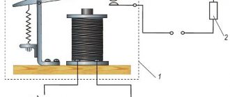
Types of power line supports
According to the manufacturing technology of reinforced concrete products, supports can be of two types:
- Vibrated. A reinforcing frame is placed in the formwork, which is filled with concrete mortar. The mold is placed on a vibrating table, which vibrates to compact the concrete;
- Centrifuged. Here the equipment is the same, only the formwork is rotated about its axis until the concrete mixture hardens. This is how round support pillars are made.
Depending on the location of the poles in the power transmission system, there is another classification:
- Anchor. This is a standard electric pole without protrusions or mortgages. They are used more often as an intermediate element of the supporting structure of power lines;
- Angular. Location – line rotation;
- End These are two pillars: one vertical, the second inclined, serving as a support. Once installed, they form the letter “L”.
The types of power transmission line supports are not limited to this. There are other classifications where the characteristics of reinforced concrete products are taken as a basis. For example, the type of reinforcing frame, the density of the concrete used, the electrical conductivity of the support, etc.
All the above-mentioned supports are assembled from SV brand racks. The abbreviation means that this is “C” - stand, “B” - vibrating. The marking also contains numbers. For example, brand SV 95-2:
- 95 is an electric pole with a length of 9.5 m;
- 2 – bending moment.
The last characteristic is important because electric poles bend under the influence of wires, wind and ice.
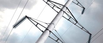
Anchor-corner metal supports 500 kV
Anchor type supports are used for:
- securing power line wires at the required distance from the ground and from each other;
- ensuring the necessary tension in the wires;
- taking on the main load when a wire breaks in adjacent areas.
These supports have a powerful, stable design and are located at the most critical points along the overhead line route. It is the anchor supports that are the final and initial ones in any power line, taking on the one-sided load from the tension of the wire. They are also installed at intersections of water obstacles, roads more than 15 meters wide, railway tracks, and other high-voltage overhead lines. Anchor supports are also installed at road turns, when the angle of rotation is small and does not exceed 20 degrees. They try to install supports of this type only at the most critical points of the route because of their high cost.
Anchor corner supports 500 kV photo
Type series 3.407.2-155.2
| No. | Brand of support | Weight, kg (with zinc coating and hardware) | Price, rub |
| 1 | US500-1 | 15828,1 | Negotiable |
| 2 | US500-1+5 | 21101,4 | Negotiable |
| 3 | US500-1+13 | 30592,9 | Negotiable |
| 4 | USK500-1 | 17171,6 | Negotiable |
| 5 | USK500-1+5 | 22443,4 | Negotiable |
| 6 | USK500-1+13 | 31940,6 | Negotiable |
| 7 | UST500-1+5 | 23113,9 | Negotiable |
| 8 | UST500-1+13 | 32612,6 | Negotiable |
| 9 | USKT500-1+5 | 23391,2 | Negotiable |
| 10 | USKT500-1+13 | 32882,5 | Negotiable |
| 11 | UO500-1 | 12983,5 | Negotiable |
| 12 | УО500-1+5 | 15389,2 | Negotiable |
| 13 | УО500-1+13 | 18964 | Negotiable |
| 14 | UOK500-1 | 14332,2 | Negotiable |
| 15 | UOK500-1+5 | 16736,7 | Negotiable |
| 16 | UOK500-1+13 | 20339,7 | Negotiable |
| 17 | PU500-1 | 12815,7 | Negotiable |
| 18 | PU500-1+5 | 14583,7 | Negotiable |
Type series 3.407.2-160.2
| No. | Brand of support | Weight, kg (with zinc coating and hardware) | Price, rub |
| 1 | US500-3 | 19281,9 | Negotiable |
| 2 | US500-3+5 | 25963 | Negotiable |
| 3 | US500-3+13 | 37312,6 | Negotiable |
| 4 | USK500-3 | 20786,6 | Negotiable |
| 5 | USK500-3+5 | 27420,2 | Negotiable |
| 6 | USK500-3+13 | 38775,7 | Negotiable |
| 7 | UST500-3+5 | 28038,3 | Negotiable |
| 8 | UST500-3+13 | 39329,4 | Negotiable |
| 9 | USKT500-3+5 | 28302,8 | Negotiable |
| 10 | USKT500-3+13 | 39602,3 | Negotiable |
| 11 | UO500-3 | 15407,7 | Negotiable |
| 12 | УО500-3+5 | 18465,1 | Negotiable |
| 13 | УО500-3+13 | 22863,9 | Negotiable |
| 14 | UOK500-3 | 16911,7 | Negotiable |
| 15 | UOK500-3+5 | 19954,1 | Negotiable |
| 16 | UOK500-3+13 | 24354,6 | Negotiable |
Standard project 3547-tm
| No. | Brand of support | Weight of support without zinc coating, kg | Total weight of hardware, kg | Price, rub |
| 1 | Anchor-corner three-post metal support with guy wires Н=17m (bolt version) type UBM17 | 12944,8 | 545,8 | Negotiable |
| 2 | Anchor-corner three-post metal support with guy wires Н=22m (bolt version) type UBM22 | 15184,2 | 654,2 | Negotiable |
| 3 | Anchor-corner three-post metal support with guy wires Н=17m (option for welding for galvanizing) type USM17 | 12203,7 | 413,7 | Negotiable |
| 4 | Anchor-corner three-post metal support with guy wires Н=22m (option for welding for galvanizing) type USM22 | 14242,5 | 507,5 | Negotiable |
Standard project 3539 tm (series 3.407-106)
| No. | Brand of support | Weight, kg | Price, rub |
| 1 | U1k | 16770 | Negotiable |
| 2 | U1k+5 | 22427 | Negotiable |
| 3 | U1k+12 | 30329 | Negotiable |
| 4 | U2k | 17877 | Negotiable |
| 5 | U2k+5 | 23565 | Negotiable |
| 6 | U2k+12 | 31442 | Negotiable |
| 7 | U2k+5P | 27727 | Negotiable |
| 8 | U2k+12P | 35507 | Negotiable |
| 9 | 16600 | Negotiable | |
| 10 | U2+5 | 22283 | Negotiable |
| 11 | U2+12 | 30160 | Negotiable |
| 12 | U2+5P | 26445 | Negotiable |
| 13 | U2+12P | 34224 | Negotiable |
| 14 | U2t | 18295 | Negotiable |
| 15 | U2+5t | 23202 | Negotiable |
| 16 | U2+12t | 31855 | Negotiable |
| 17 | 15521 | Negotiable | |
| 18 | У1+5 | 21204 | Negotiable |
| 19 | У1+12 | 29081 | Negotiable |
| 20 | U1+5P | 26366 | Negotiable |
| 21 | U1+12P | 33145 | Negotiable |
| 22 | U1t | 17216 | Negotiable |
| 23 | U1+5t | 22889 | Negotiable |
| 24 | U1+12t | 30776 | Negotiable |
| 25 | U1k+5P | 25815 | Negotiable |
| 26 | U1k+12P | 34394 | Negotiable |
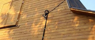
How to install electricity poles
Rules for installing electric poles are based on the weight of the reinforced concrete product. Therefore, during the installation process they use special equipment:
- a crane for lifting the support and installing it in the prepared well;
- a tractor that brings the poles to the installation site.
There are two main technologies for installation in the ground:
- The electrical support is simply immersed in the ground. No additional elements are used for this;
- With installation on a base.
The second position is two different approaches to installation work. One option is to insert a stand into a prepared well, which is 20-30 cm larger than the cross-section of the reinforced concrete product. After the support is aligned vertically, its lower part inside the well is filled with concrete mortar. Installers often call this design either frame or frame.
The second option is installation on metal or reinforced concrete piles. That is, before installing an electric pole, a pile is driven into the ground on which it will rest.
But the installation process itself begins with the assembly of the support. That is, a traverse and a grounding descent are installed on it. After this, insulators are screwed onto the traverse. A stencil must be printed that provides information about when the electric pole was installed and the serial number of the element in the electrical system network.
All technologies necessarily involve the process of waterproofing part of the electrical network elements that are immersed in the ground. Hot bitumen is usually used for this. Depending on the type of soil and the mass of the reinforced concrete product, the supporting structure is immersed to a depth of 1.2-2.0 m.
If traditional installation technology is used, that is, not frame, then the gaps between the walls of the well and the pillar are filled with either excavated soil or fine or medium-sized crushed stone. The latter can be replaced with gravel. At the same time, the bedding is compacted well.
The installation of an end-type electricity pole is carried out in the same way, but first a vertical support is mounted, which is immediately fixed in the ground. And then the second inclined one. Both racks are connected to each other by clamps, cross ties or special crossbars. According to the technology, spacers or braces are temporarily installed.
Attention! Backfilling soil into the well gap or pouring concrete mortar can only be done after the installation height of the supporting structure has been checked. If the height is greater than required, the well is deepened. If less, it is covered with soil or crushed stone with thorough compaction.
Vibrating racks for supports up to 35 kV
| Photo | Name | Documentation | Slab dimensions, mm | Volume | Weight | Concrete class/grade | Frost resistance | Water - impermeability | Price* | Availability | |||||
| length | width | height | m3 | TN | |||||||||||
| b | b1 | b2 | h1 | h1 | |||||||||||
| SV164-10.3 | TU 5863-007-00113557-94 | 16400 | 390-210 | 370 | 190 | 380 | 200 | 1,42 | 3,55 | B 30/400 | F 200 | W 6 | from 38,705 rub. | To order from 1 day | |
| SV164-10.7 | TU 5863-007-00113557-94 | 16400 | 390-211 | 370 | 190 | 380 | 200 | 1,42 | 3,55 | B 30/400 | F 200 | W 6 | from 37,450 rub. | To order from 1 day | |
| SV164-12 | TU 5863-007-00113557-94 | 16400 | 390-212 | 370 | 190 | 380 | 200 | 1,42 | 3,55 | B 30/400 | F 200 | W 6 | from 38,650 rub. | To order from 1 day | |
| SV164-20 | TU 5863-007-00113557-94 | 16400 | 390-212 | 370 | 190 | 380 | 200 | 1,42 | 3,55 | B 30/400 | F 200 | W 6 | from 61,110 rub. | To order from 1 day | |
* The price of products is calculated individually and depends on the volume of the order, method and place of delivery, and other conditions. The company's managers will help you place your order and choose the optimal terms of cooperation.
Advantages of reinforced concrete pillars
Power line supports made of reinforced concrete have:
- High strength. They can easily withstand not only strong wind loads, but also impacts from collisions with cars and other vehicles;
- One hundred percent environmentally friendly. There are no materials in the design that, under changing humidity and temperature or under the influence of the sun, release substances harmful to humans into the air;
- Service life – 100-150 years;
- Minimum financial and labor costs for repair work;
- Dielectric properties.
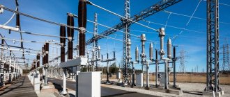
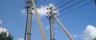
Electrical supports are an element of the architecture of cities, towns and transport interchanges. Not the most presentable appearance does not repel. It is clear that their main task is to create safe conditions for the transportation of electricity.
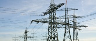
Intermediate metal supports 500kV
Intermediate type supports have a much simpler and less expensive design. Their main purpose is only to maintain wires at specified distances. They do not carry any special load, and only at the turning points of the route at angles exceeding 20 degrees, the design of the intermediate corner supports is made somewhat reinforced.
Intermediate supports make up up to 90% of all high-voltage line supports. They come in several types in shape and design:
- corner three-post with guy wires;
- cable-stayed;
- free-standing;
- in the form of a portal (PB3-1, PP500-3, PUB-2) with guy wires.
Intermediate supports are divided into branch and transposition, cross, elevated or lowered.
Intermediate supports 500 kV photo
Type series 3.407.2-155.1
| No. | Brand of support | Weight, kg (with zinc coating and hardware) | Price, rub |
| 1 | PP500-1 | 6830 | Negotiable |
| 2 | PP500-1-I | 6771 | Negotiable |
| 3 | PP500-1-II | 6712 | Negotiable |
| 4 | PP500-1-III | 6653 | Negotiable |
| 5 | PP500-1-IV | 6595 | Negotiable |
| 6 | PP500-3 | 7226 | Negotiable |
| 7 | PP500-3-I | 7163 | Negotiable |
| 8 | PP500-3-II | 7098 | Negotiable |
| 9 | PP500-3-III | 7035 | Negotiable |
| 10 | PP500-3-IV | 6972 | Negotiable |
| 11 | PS500-1 | 12115,8 | Negotiable |
| 12 | PS500-1+5 | 14331,1 | Negotiable |
| 13 | PS500-1+10 | 18669,1 | Negotiable |
Type series 3.407.2-160.1
| No. | Brand of support | Weight, kg (with zinc coating and hardware) | Price, rub |
| 1 | PP500-5 | 8995,6 | Negotiable |
| 2 | PP500-5-I | 8842,2 | Negotiable |
| 3 | PP500-5-II | 8688 | Negotiable |
| 4 | PP500-5-III | 8534,6 | Negotiable |
| 5 | PP500-5-IV | 8381,4 | Negotiable |
| 6 | PP500-7 | 12043,6 | Negotiable |
| 7 | PP500-7-I | 11839,6 | Negotiable |
| 8 | PP500-7-II | 11562 | Negotiable |
| 9 | PP500-7-III | 11433,2 | Negotiable |
| 10 | PP500-7-IV | 11229,4 | Negotiable |
| 11 | PP500-5+3 | 9434,6 | Negotiable |
| 12 | PS500-3 | 16694,6 | Negotiable |
| 13 | PS500-3+5 | 19603,4 | Negotiable |
| 14 | PS500-3+10 | 23937,1 | Negotiable |
Standard project 3539tm (series 3.407-106)
Intermediate supports on guy wires
| No. | Brand of support | Weight, kg | Price, rub |
| 1 | PB1 | 6980 | Negotiable |
| 2 | PB2 | 7163 | Negotiable |
| 3 | PB3 | 7785 | Negotiable |
| 4 | PB4 | 8256 | Negotiable |
| 5 | PB5 | 8691 | Negotiable |
Intermediate corner supports with guy wires
| No. | Brand of support | Weight, kg | Price, rub |
| 1 | PUB2 | 10064 | Negotiable |
| 2 | PUB5 | 9937 | Negotiable |
| 3 | PUB20 | 14219 | Negotiable |
Intermediate sloped supports on guy wires
| No. | Brand of support | Weight, kg | Price, rub |
| 1 | PB1-I | 6916 | Negotiable |
| 2 | PB1-II | 5849 | Negotiable |
| 3 | PB1-III | 5783 | Negotiable |
| 4 | PB1-IV | 5717 | Negotiable |
| 5 | PB2-I | 7098 | Negotiable |
| 6 | PB2-II | 7032 | Negotiable |
| 7 | PB2-III | 6967 | Negotiable |
| 8 | PB2-IV | 6901 | Negotiable |
| 9 | PB3-I | 7710 | Negotiable |
| 10 | PB3-II | 7632 | Negotiable |
| 11 | PB3-III | 7553 | Negotiable |
| 12 | PB3-IV | 7484 | Negotiable |
| 13 | PB4-I | 8177 | Negotiable |
| 14 | PB4-II | 8099 | Negotiable |
| 15 | PB4-III | 8021 | Negotiable |
| 16 | PB4-IV | 7942 | Negotiable |
| 17 | PB5-I | 8612 | Negotiable |
| 18 | PB5-II | 8534 | Negotiable |
| 19 | PB5-III | 8456 | Negotiable |
| 20 | PB5-IV | 8317 | Negotiable |
Intermediate single-post freestanding supports
| No. | Brand of support | Weight, kg | Price, rub |
| 1 | 11192 | Negotiable | |
| 2 | P1+5 | 13699 | Negotiable |
| 3 | P1+10 | 16180 | Negotiable |
| 4 | 11869 | Negotiable | |
| 5 | P2+5 | 14376 | Negotiable |
| 6 | P2+10 | 16857 | Negotiable |
| 7 | P1+5P | 14773 | Negotiable |
| 8 | P1+10P | 16496 | Negotiable |
| 9 | P2+5P | 15450 | Negotiable |
| 10 | P2+10P | 17833 | Negotiable |
Support manufacturing technology
The main stage of production of support logs still involves mechanical processing in order to form technological openings with holes. Horizontal ends are protected using special pastes already at the basic finishing stage. If necessary, existing nicks, chips and webbing are corrected - they can be eliminated provided that the depth is no more than 10% of the diameter of the workpiece. To maintain accuracy during the machining process, the production of wooden power line poles at some enterprises involves the use of special templates. For example, the parameters of cuts and notches are checked using them.
Next begins the drying stage, which prepares the wood for impregnation. According to regulations, protective agents can only be applied if the humidity of the array is no more than 28%. Barked logs are dried in special thermal chambers, which have an unusual design. The fact is that in such units, hot air flows are not directed towards the workpiece, but circulate around it. Thus, cracking and overheating of the material is prevented.
Features of supports SV 110-35, SV 110-5
Among the SV supports with a length of 110 decimeters there are 2 varieties:
- SV 110-35.
Reinforced concrete racks SV 110-35 are used in the construction and reconstruction of power lines with a voltage of 0.38 kV. The weight of one rack is 1.13 tons, the bending moment is 3.5 tf*m, the maximum load into a vehicle is 20 tons - 18 units. - SV 110-5.
These racks are a reinforced concrete trapezoidal pole used for laying power lines with a voltage of 0.4-10 kV. The weight of the support is 1.13 tons, but its bending moment is much greater than that of the previous type of stands and amounts to 5.0 tf*m. Maximum load in a vehicle is 20 tons - 18 units.