All distribution boards must perform 3 main tasks:
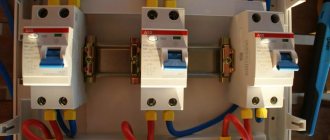
- cable protection against overloads and short circuits
For this purpose, automatic switches are installed in switchboards. They are primarily designed to protect the cable, and not the equipment connected to it, as many still think.
In case of overloads or overheating, the thermal release is activated and protects the wiring insulation from melting. In the event of an obvious short circuit, it is no longer the thermal, but the electromagnetic release that is triggered.
- protecting people from electric shock
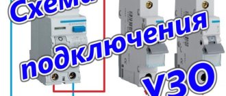
This is ensured by installing RCDs or differential circuit breakers.
- protection of equipment from voltage surges
Unfortunately, power surges often occur in our networks. The machines do not react to this, since they are simply not designed for such protection.
The RCD is also not designed to be triggered by overvoltage. To do this, you will need modular voltage relays or UZM - multifunctional protection devices.
They set certain upper and lower voltage limits. As soon as there is a jump, or, conversely, a sharp decrease in the parameters of the electrical network, this relay (UZM) is triggered and turns off the power.
Differences in assembling three and single-phase shields
What is the difference between assembling a 3-phase shield, in order to ensure the above tasks, from assembling a single-phase one? It is clear that single-phase is an order of magnitude simpler than three-phase.
There is only a single phase, zero and protective ground. In 3-phase, the same zero, protective grounding and already 3 phases come to your shield.
On the one hand, this gives you the opportunity to connect a much larger load and receive more power from the energy transmission organization for connection. But on the other hand, this always incurs high costs, plus the need for competent distribution of this very load.
You cannot (at least it will not be correct) connect all the devices in the house to one phase, and keep the other two as a reserve. This threatens the load imbalance between phases.
As a result, the voltage on one of them will be low, and on the other two it will jump by several units or even tens of volts. Of course, you can protect yourself from this by installing the appropriate devices (for example, phase switches), but your neighbors will suffer due to an illiterately assembled 3-phase panel.
And not through your own fault or the fault of the energy supply organization, but precisely because of you.
Therefore, the main task and difference of a three-phase shield is the need to distribute the load as evenly as possible across all phases.
There are many options for assembling and completing three-phase panels. We will not consider the simplest ones with a minimum amount of introductory equipment.
We will choose ones that are more complex in configuration, but at the same time quite versatile. Due to the sharp increase in the number of electrical appliances in our apartments and houses, they have recently become increasingly popular.
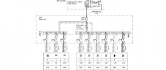
A simple diagram for connecting the electrical panel of a private house 15 kW
The simplest budget option for assembling a metering board is presented below. Only the most necessary elements are used here:
1. Metal hinged shield, protection degree ip54 or higher.
2. Plastic box 3 modules, with eyes for seals
3. Three-pole Protective circuit breaker, characteristic C25 (for an allocated power of 15 kW this rating is needed)
4. Electric energy meter (meter) 3-phase 380V
5. Distribution switching block, capable of connecting wires with a cross-section of up to 16 mm2.
Scheme of a simple electrical metering panel for a private house 15 kW, TN-CS grounding system:
Simple metering panel, TT grounding system
This option is often used as a temporary one, for example, to connect a change house during construction, as it has few means of protection.
For your house in which you plan to live permanently, even for a country house, I recommend using the following assembly:
Assembly on differential automatics
Advantages:
- Each line is protected from short circuits, overloads, and leaks. And all this is just one device.
- It’s easier to identify the problem area in case of damage
- no zero buses
- you have complete freedom in grouping devices in the shield
- easy to distribute the load across phases
Flaws:
- large dimensions of the shield and a large number of modular devices (from 72 pieces or more)
- very expensive
A differential machine is equipment that is installed on a separate line, like a regular machine, but also includes leakage protection (differential protection).
Although this is the best option, it is also the most expensive. Therefore it is used extremely rarely.
The total amount of such an assembly can reach 200 thousand rubles.
Relatively speaking, how many outgoing group lines you have, the same number of differential automatic machines will be needed.
At the same time, in order to understand in case of possible accidents why such a machine has switched off, from a leak or a short circuit, it is recommended to use models with an indication of the cause of operation.
At the beginning of the circuit, an input device is mounted - a switch. From it you supply power to the voltage relay.
Next, through cross-modules you divide the load into diffs. You run one phase for each machine.
If it later turns out that one or another line overloads any of the phases, you just need to swap them on one of the cross-modules, transferring the wires from one busbar to another.
If you are not limited by budget, then this is the best option for assembling and completing a three-phase panel.
Load distribution algorithm across three phases
As already mentioned, it is necessary to collect the entire single-phase load and distribute it evenly between the phases. Moreover, the trick is to select everything so that powerful devices connected to one phase do not cause an overload shutdown. This is possible if the total power of the operating devices is no more than the nominal value, or if these devices do not operate simultaneously.
A 380 V apartment panel may not be very large
General principles of load grouping for automatic machines
The most reliable and easy-to-maintain scheme is when for each group of consumers or powerful device there is a separate machine, and together with it an RCD. But such a scheme, firstly, is expensive, and secondly, it simply requires a huge cabinet, which is also not cheap. Therefore, they try to connect several lines to one machine, but they must be combined following a certain logic. Otherwise, it will be very difficult to figure out what’s what when the machine is triggered. You should adhere to the following rules:
- Connect sockets and lighting in one room through different machines. In this case, if there are problems in one of the groups, the room will not be completely de-energized.
- “Wet” rooms - bath, kitchen, bathhouse - should not be grouped with “dry” ones. Firstly, in rooms with increased danger, machines should have different parameters, and secondly, it is in wet rooms that problems usually arise.
- Street lighting and street sockets generally should be separate - on separate machines. Outbuildings can be connected to them.
- The power supply for the gate drive and security lighting are also separate machines.
Make a plan for a three-phase electrical panel - distribute the load between three phases
- Separate power lines and separate circuit breakers and RCDs are installed on both powerful household appliances (electric stoves and electric ovens) and those that use water. As a last resort, you can combine, say, a washing machine and a dishwasher. You can also combine instantaneous and storage water heaters into one group, but on the condition that they will not turn on at the same time, since they are highly likely to trigger an overload shutdown. Moreover, they can be connected to one machine only if they are installed in the same room, otherwise you will not understand anything if damaged.
To make it easier to form groups, make a list of lines and the load on them. The room, line name and power of the connected load must be indicated. Looking at this table, following the rules described above, you assemble groups. At the same time, you must also ensure that the load is distributed more or less evenly.
Checking groups
After you have sketched out the groups on paper, check them. Sit down and think about what will happen if each of the machines works, how catastrophic the consequences will be for each room.
You can assemble a 380 V switchboard for a private home with your own hands, but you must first figure out how to distribute the load
For example, if in a two-story cottage you connect all the sockets of the first floor and the lighting of the second to one machine, and the lighting of the first, the sockets of the second to another, and the equipment to the third, then when any of the machines is triggered the situation will be terrible.
This is how we lose situations with each machine being turned off. It is advisable that there be either working sockets in the room or that they be in the adjacent one. Then, if necessary, it will be possible to connect equipment and lighting.
RCD and single-pole circuit breakers
Assembly advantages:
- economically
- a small shield is required (from 54 to 72 modules)
Flaws:
- not clear grouping of lines
- impossibility of simply making changes in load redistribution across phases
- presence of zero tires
This is one of the simplest and most common options for assembling and designing three-phase panels. This is explained, of course, by its cheapness in relation to others.
However, this method does not allow making significant changes to the switchboard in the future. This is primarily due to the distribution of load across phases.
The one who initially designs the shield, based on certain considerations and technical conditions, divides the load accordingly into phases. As it seems to him, maintaining uniformity.
However, this is all preliminary division. Since no one knows the real consumption. And only over time, through measurements, can you see the actual picture. And it may differ significantly from the previously designed one.
And in order to somehow equalize the loads, we have to redo almost half of the entire panel. Leave it as is, and you will definitely encounter problems in the future:
- voltage imbalance
- heating of the zero bus with possible burnout of the zero
- overloaded machines and the consequences of this
There is an even more simplified version of this configuration method.
Improving the budget scheme
Now let’s take a closer look at the option with two-pole circuit breakers, which was preferred by the customer. Its price is about 90 thousand rubles, versus 80 thousand for a shield on single-pole networks. And two-terminal networks give us nothing more or less than that same zero pole for each line. And this will make it possible to quickly put into operation all the lines under the triggered RCD, except for the problematic one, including in the case of a leak from scratch.
By disconnecting the problem line with a two-terminal device, we localize the problem within the boundaries of this problem line. The remaining lines remain in operation. Well, yes. Everyone has their own zero. And the problematic one is now disabled. The procedure for localization is similar to what I described just above for single-pole networks. Yes, you have to pay for this opportunity. At today's prices, this is about 650 rubles for each line minus the cost of zero buses, which are not needed in a circuit with two-terminal networks.
In some cases, you will have to use a box of a larger standard size than in the version with single-pole circuit breakers. But in this case, with 17 groups, both options on automatic machines required the same box for 72 modules as with two-terminal networks. The lion's share of the space in the box (60%) in this scheme is occupied by switches, RCDs, UZMs, cross-modules and a non-switchable group. And there’s no way to fit three groups of machines onto half a DIN rail, even with 18 modules. But in the version with single-pole circuits, you can safely add another 4-pole RCD with a group of five circuit breakers to this box.
And for this circuit there is also an alternative to phase-by-phase differential protection with two-pole RCDs. Details in the second review of three-phase switchboard diagrams.
RCD at the input and single-pole circuit breakers
Advantages:
- cheapest option
- small shield (up to 32 modules)
Flaws:
- there is practically no grouping of lines
- there is no possibility of changing the load by phase
- there are zero buses
- possible false triggering of RCD
Here, only one RCD is used at the input (except for consumers that cannot be disconnected) and then the load is distributed through single-pole circuits. According to clause 7.1.83 of the PUE, you may be limited in the choice of the number of connected lines.
If you ignore this rule, then false alarms of the RCD are quite likely. At the same time, you will rack your brains for a long time wondering whether it worked as a protection or falsely.
Therefore, it is better to look for intermediate options for completing a three-phase panel.
Switchboard layout
I have already discussed in detail the basic principles of layout when designing and assembling distribution boards. In the electrical panel under consideration, the layout (i.e., the arrangement of devices inside the electrical panel itself) is adopted in a row in groups.
Enter
A load switch and a voltage control relay are installed on the first DIN rail at the input of the distribution board.
The load switch allows, if necessary, to completely de-energize the entire electrical panel for repair or maintenance work on both the switchboard and the entire apartment electrical wiring as a whole.
The ZUBR voltage control relay provides protection of the home electrical network from surges and surges in voltage in the supply network, as well as protection from zero loss.
Later, depending on financial capabilities and the purchase of equipment for a low-current network, the customer will add here both a circuit breaker for a low-current switchboard and other devices that are still being considered.
Kitchen
A group kitchen RCD is installed on the second DIN rail, and after it there are automatic switches for kitchen consumers:
— electric oven;
- kitchen sockets;
- kitchen air conditioner.
Room sockets
A group RCD of socket groups is mounted on the third DIN rail, followed by automatic switches in the rooms:
- room sockets;
— two air conditioners;
- apartment lighting.
Two-pole circuit breakers + cross modules + RCD
Advantages:
- the ability to easily distribute the load across phases
- visual grouping of lines
- Convenient connection of power supply and outgoing conductors
- no zero tires
Flaws:
- overall dimensions of the shield (from 96 to 144 modules)
- relatively expensive
When you assemble a shield according to the first option using differential machines, you pass the phase and neutral conductors through it. Plus, there is no need for an RCD.
If for economic reasons you cannot afford differential circuit breakers, you will still have to group the outgoing lines at the RCD.
However, in order for everything to be repairable and easy to make changes to the circuit without radical reconstructions and rewiring of wires, instead of conventional single-phase modular circuit breakers, it is enough to use two-pole circuit breakers.
Externally, they look like two single modular single-terminal circuits assembled together.
To assemble the circuit, connect the zeros in one or another group of 4-pole RCDs. You pass all the phases through them and then send them to the cross modules. After which the phases are distributed among the machines.
Sequence of correct installation of an electrical panel
To ensure that the electrical panel in your home is installed correctly, you should use only high-quality electrical products, as well as consumables. Only after installation is completed, operating voltage is supplied to the panel.
The correct assembly of a three-phase electrical panel has the following sequence:
- Installation of an introductory machine. The device rating must cover the maximum power consumption. Since 3 phases will be brought into the house, the voltage between them will be 380 V, it is necessary to install a three-pole circuit breaker. To save money, it is not recommended to install 3 single-pole circuit breakers and connect them with a special strip. The input machine is installed in the upper left corner of the shield and is marked accordingly.
- After the introductory machine, it is necessary to install an RCD. The rating of the device must correspond to the rating of the input switch. You should also pay attention to the cut-off current - the lower this indicator, the faster the RCD will turn off the network. There are differential circuit breakers that include protective functions against short circuits and shutdown the network when a leakage current occurs (RCD and standard switch). It is easier to use such a product, but its cost is quite high.
- To the right of the RCD, at a short distance, a zero bus is mounted. Modern busbars provide a plastic dielectric between the copper strip and the shield body. This is done so that if the zero burns out and a phase gets on it, the electrical panel does not end up under life-threatening voltage.
- Measuring instruments and voltage relays can also be placed on the strip with the input circuit breaker, RCD and zero bus. If you install a voltmeter and an ammeter in a three-phase network, then you must select products that display both linear and phase loads. And also capable of showing data on each phase separately.
- The lower DIN rail contains automatic switches for power and lighting lines. In order not to get confused and not constantly look at the rating of the machines, lighting line products should be located at a short distance from the power switches.
Read also: Cutting threads on a 16k20 machine
After assembling the panel, it can be mounted to the wall and wires from consumers to the machines can be connected. An example of an electrical panel diagram, the number of machines can vary depending on the wishes of the owner.
If the electricity metering panel with a voltage of 380 V is not located on the street, then it is first installed in front of the input machine. But installing a device to monitor electricity consumption in the house is inconvenient, so inspectors (to save time and the absence of owners) must take readings on the street.
Doubtful ideas sometimes shoot out
Well, one more, fourth option. At first glance, it may seem dubious and unreasonable. Upon closer examination, it turns out to be quite viable and allows you to get the functionality of a shield on automatic machines for significantly less money. The point is to provide each line with its own protection against leakage currents, i.e. A 2-pole RCD in addition to a single-pole circuit breaker. This personal protection will take 3 modules on a DIN rail for each line, i.e. you will need one and a half times more space in the box than for difautomatic machines, but each line will receive its own two poles - zero and phase and, more importantly, its own protection against leakage currents.
If we take into account that we do not need bulky 4-pole RCDs as in other alternatives, and it is quite possible to get by with one 4x7 cross-module to distribute power across phases, then the proposed circuit fits quite easily into the same 4x18 box. And there's still room left.
Now for the price. A type A differential with a nominal value of 16A costs 5.3 thousand rubles today. A combination of RCD A25/0.03 + automatic C16 will cost 3.5 thousand. Those. we will also save 1800 rubles on each line. Thus, the scheme, which was dubious at first glance, turned out to be similar in functionality to the scheme on difavtomats with a shield price of about 114 thousand rubles.
Notes and additions
- The color identification of conductors in this switchboard is made in accordance with the requirements of GOST R 50462–92, which was in force from January 1, 1994 to December 31, 2010. Currently, the requirements of GOST 33542–2015 should be followed.
- Type A UDT operates with sinusoidal and pulsating direct currents.
- Input block is a functional block of the apartment panel through which electricity is supplied to the switchboard, containing switching and protective devices, and also includes a part of the switchboard volume intended for placing, fastening and connecting input conductors to the internal electrical circuits of the switchboard.
- Distribution block is a functional block of an apartment panel that contains protective devices for final electrical circuits and includes a part of the switchboard volume intended for placing, fastening and connecting the conductors of these electrical circuits to the internal electrical circuits of the switchboard.
- This control panel takes into account “Changes 1”, which were adopted in March 2017 by the International Electrotechnical Commission to the IEC 60364-4-41:2005 standard (on the basis of which the national standard GOST R 50571.3-2009 was created and is currently in force). Let me remind you that these “Changes 1” require mandatory additional protection by means of UDTs with a rated differential current not exceeding 30 mA for all final electrical lighting circuits, the lamps of which are located in domestic premises. This requirement is logical, since in residential premises lamps are often installed within the reach of a hand. Moreover, the lamps are used by ordinary people.
Design
The apartment panel in question meets the requirements for class II electrical equipment. The box-type control panel (Fig. 2 and 3) is designed for hidden installation in a niche on a vertical wall. The KShch body is a metal box with a single door measuring 1134x560x120 mm. It provides IP31 degree of protection.
Rice. 2. External view of the apartment panel with a closed (A) and open door (B) (based on Figure 6.17 from the book [1] by Yu.V. Kharechko)
The switchboard housing contains a mounting panel designed for installation of circuit breakers, differential current devices, terminal blocks, busbars and other electrical equipment. The panel covers are made of insulating material. They prevent access to live parts of the switchboard. The mounting panel is 500 mm wide.
Rice. 3. External view of the apartment panel with the panel covers removed (based on Figure 6.18 from the book [1] by Yu.V. Kharechko)
The upper part of the mounting panel KShch (Fig. 4) is used to make an input block and a distribution block. The following electrical equipment is installed on this part of the panel:
- input spring clamp blocks, which are designed to connect the phase, neutral and protective conductors of the electrical input circuit, as well as the internal electrical circuit of the control panel. These terminal blocks allow the connection of conductors with a cross-section of up to 16 mm2;
- input four-pole circuit breaker QF1 series S 200 with all protected poles, which has a rated current of 40 A, a rated short-circuit switching capacity of 6000 A and instantaneous tripping type C;
- four-pole circuit breaker QF2 series S 200 with all protected poles, which has a rated current of 16 A, rated short-circuit switching capacity of 6000 A, instantaneous tripping type C;
- four-pole SPD FV1–FV4 Type 2 with a maximum discharge current of 40 kA, rated discharge current of 20 kA, rated voltage of 230 V and protection voltage level of 1400 V;
- busbars L1, L2, L3 and N, made on the basis of a four-pole distribution block with a rated current of 125 A and allowing the connection of 10 conductors with a cross-section of up to 16 mm2 and 2 conductors with a cross-section of up to 35 mm2;
- PE protective busbar, which is part of the KSh busbars, which is made on the basis of a busbar that allows the connection of 4 conductors with a cross-section of up to 10 mm2 and 19 conductors with a cross-section of up to 4 mm2;
- four-pole VDT1 QF3 and QF7 type A, for general use, having a rated current of 40 A and a rated residual current of 0.03 A;
- two-pole circuit breakers QF4, QF5, QF6 series S 200 with all protected poles, which have a rated current of 10 A, a rated short-circuit switching capacity of 6000 A and instantaneous tripping type C;
- two-pole circuit breakers QF8, QF9, QF10 series S 200 with all protected poles, which have a rated current of 16 A, a rated short-circuit switching capacity of 6000 A and instantaneous tripping type C;
- three-pole spring terminal blocks for connecting phase, neutral and protective conductors with a cross-section of up to 4 mm2 of single-phase final electrical circuits (groups 1–6).
Rice.
4. The upper part of the control panel panel with the cover removed. The figure shows: 1 – input terminal blocks; 2 – automatic switch QF1; 3 – automatic switch QF2; 4 – busbars L1, L2, L3, N; 5 – VDT QF20; 6 – PE protective busbar; 7 – SPD FV1–FV4; 8 – VDT QF11; 9 – VDT QF7; 10 – automatic switches QF8, QF9 and QF10; 11 – VDT QF3; 12 – automatic switches QF4, QF5 and QF6; 13 – three-pole terminal blocks for connecting conductors of single-phase electrical circuits (group 1–6) (based on Figure 6.19 from the book [1] by author Yu.V. Kharechko) The lower part of the switchboard mounting panel is used to make a distribution block (Figure 5) . The following electrical equipment is installed on this panel:
- four-pole RCCBs QF11, QF15, QF20, QF27 and QF29 type A, for general use, having a rated current of 40 A and a rated residual current of 0.03 A;
- four-pole circuit breakers QF26 and QF28 series S 200 with all protected poles, which have a rated current of 16 A, rated short-circuit switching capacity of 6000 A, instantaneous tripping type C;
- two-pole circuit breakers QF12–QF14, QF16–QF18, QF19, QF21 and QF22 of the S 200 series with all protected poles, which have a rated current of 16 A, a rated short-circuit switching capacity of 6000 A, instantaneous tripping type C;
- two-pole RCBOs QF23, QF24 and QF25 series DS 941 type A, for general use, having a rated current of 16 A, rated residual current of 0.03 A, rated short-circuit switching capacity of 4500 A, instantaneous tripping type C;
- three-pole spring terminal blocks for connecting phase, neutral and protective conductors with a cross-section of up to 4 mm2 of single-phase group electrical circuits (group 7–18);
- five-pole spring terminal blocks for connecting phase, neutral and protective conductors with a cross-section of up to 4 mm2 of three-phase group electrical circuits (groups 19 and 20).
Rice.
5. The lower part of the housing panel with the cover removed. The figure shows: 1 – RCCB QF27; 2 – VDT QF20; 3 – automatic switches QF19, QF21 and QF22; 4 – VDT QF15; 5 – VDT QF11; 6 – automatic switches QF12, QF13 and QF14; 7 – RCBOs QF23, QF24 and QF25; 8 – automatic switch QF26; 9 and 10 – three-pole terminal blocks for connecting conductors of single-phase electrical circuits (groups 13–18 and 7–12); 11 – VDT QF29; 12 – automatic switch QF28; 13 and 14 – five-pole terminal blocks for connecting conductors of three-phase electrical circuits (groups 19 and 20) (based on Figure 6.20 from the book [1] by Yu.V. Kharechko) Input terminal blocks intended for connecting phase conductors are gray in color , neutral conductors – blue, protective conductors – yellow-green. The terminal blocks for phase conductors and neutral conductors are connected in pairs using two jumpers.
Automatic switches QF1 and QF2 are connected to the phase and neutral input blocks of the KShch terminals. The QF1 circuit breaker is connected to busbars, which include three phase busbars (L1, L2, L3) and a neutral busbar (N), and the QF2 circuit breaker is connected to a four-pole SPD FV1–FV4.
The internal electrical circuits of the switchgear from the input terminal blocks to the busbars (including the PE protective busbar) and from the busbars to four-pole RCCBs are made of insulated flexible copper conductors with a cross-section of 10 mm2. The remaining electrical circuits inside the switchboard up to the terminal blocks intended for connecting the conductors of the final electrical circuits are made of insulated flexible copper conductors with a cross-section of 4 mm2.
For every three two-pole circuit breakers connected to one four-pole RCCB, the input (upper) terminals of the poles to which the neutral conductors must be connected are connected to each other by a connecting bus with blue insulation. This connection bar is a PS1/57NA type connection bar cut into pieces containing five pins, two of which have been removed. It is used to make an electrical circuit of a neutral conductor. The output (lower) terminal of the switching neutral pole of a four-pole RCCB is connected via a neutral conductor to one of the specified input terminals of two-pole circuit breakers.
Metal mounting rails of the control panel, on which the terminal blocks are installed, are used as protective conductors. The input protective terminal block forms electrical contact with the mounting rail. All terminal blocks intended for connecting protective conductors of final electrical circuits also form electrical contacts with mounting rails. By means of the specified terminal blocks and the mounting rails on which they are installed, internal electrical circuits of protective conductors are formed in the control panel. These mounting rails are secured to the mounting frame using special insulators, which prevent their electrical connection with other metal elements of the control panel mounting panel. These mounting rails are connected by protective conductors to the protective busbar of the control panel, which is connected by a protective conductor to one of the terminals of the input protective terminal block.
Who connects and where to get permission?
Before connection, an agreement is drawn up with the electrical network organization and the owner of the site. Connection should be made with equipment specially designed for this purpose - these are HEGEL 733 clamps up to 35 sq. mm
All work inside the site on wiring electrical cables is carried out by the owner of the site himself. After this, you will need to draw up a diagram of the location of electrical communications; if the network organization approves the work carried out, then within 30 days they are required by law to make the connection, with the issuance of documents.
Application and permission to connect to the city power grid:
What is the connection cost?
The cost of connection depends on the region; each region has its own tariffs, but on average it does not exceed 550 rubles for connecting to a 15 kW line. This depends on the distance to nearby power grids.
Option 5
The fifth option presents a diagram of a three-phase shield without an incoming RCD, but using single-phase automatic circuit breakers for some consumers. RCBOs are placed one per group and therefore their number can be equal to the number of groups. This way all consumer groups will be independent of each other. That is, if a current leak occurs in one device, only the circuit breaker to which it is connected will turn off. When using an RCD with 3-5 circuit breakers, when the RCD is triggered, 3-5 groups will be switched off, respectively. And this is no longer very convenient for the exploitation of consumers.
Programs for drawing electrical circuits
But there are three main schemes of an electrical project, but on which not only the entire project is based, but also all future work of electricians or electricians. It is performed when there is a need to introduce serious changes to the project based on the results of an inspection of an existing electrical installation and the identification of inconsistencies with existing standards and rules. In addition to design and executive diagrams, single-line diagrams are as follows: structural – contain general data about the electrical installation, which is expressed in indicating the connections of power elements, in particular, transformers, power lines, tie-in points and much more; functional - they are made primarily for the purpose of abstractly conveying the actions of the mechanisms to which the power supply is connected; their interaction with each other and how they affect the general state of affairs from a safety point of view are also indicated. There are several wonderful free programs for drawing electrical circuits in a house or apartment in Russian: Electrical Compass. At its core, there are no particularly fundamental differences between them, with the exception of the purpose of each type
It is important to know that all specified elements and dimensions must be accurate and clear. Therefore, upon completion of the work, the customer receives not only a diagram, but also recommendations for eliminating defects identified during the inspection. Electrical installation work and safe operation of the electrical network will depend on such a scheme. There are several wonderful free programs for drawing electrical circuits in a house and apartment in Russian: Compass electrician
When compiled correctly, complete electrical and fire safety for people and objects is ensured.
New design technologies
Single-line diagrams can be executive and calculation. Depending on the type of electrical circuit, the stages of its creation will be different: In the executive electrical circuit, the first step in construction will be the compilation of calculation and computational materials. Up to the connection point, the electricity supplier and the network owner bear operational responsibility; after that, the electricity consumer bears operational responsibility. The calculated single-line electrical diagram is performed for new construction projects. These are automatic machines, RCDs, contactors, switches and other parts of the electrical network. Such a single-line power supply diagram for a particular residential or non-residential facility is a key document that is responsible for the operational responsibilities of different parties.
Single-line electrical diagram of power supply To simplify the drawings and their perception, various techniques are used. This connection is perfectly demonstrated by a single-line diagram of a KTP transformer: Photo - single-line diagram of a KTP transformer Examples of what a single-line typical power supply diagram of a clinic, apartment, country or country house, factory or other premises should include: The point where the object is connected to the electrical network; All ASU input and distribution devices; The point and brand of the device that is used to connect the room in most cases, the parameters of the shield are also needed; It is necessary not only to draw the power cable, but also to mark its cross-section and brand on the diagram; sometimes craftsmen mark the nominal value; The project must contain data about the rated and maximum currents of the equipment used at the facility. A general idea of a linear power supply diagram. A diagram is a graphical representation of any structural elements indicated on the drawings. Electrical installation work and safe operation of the electrical network will depend on such a scheme.
But at the same time, single-phase wiring is indicated by one line with one stroke. It indicates everything that an electrician needs to install the electrical wiring of an apartment, except for connecting sockets and lamps at the installation site. The number in such a diagram is responsible for determining the number of phases, and the line crossed out by oblique segments is the definition of the phase. How to read electrical diagrams. Lesson #6