Is the Polish grid suitable for receiving digital television?
The Polish mesh antenna at one time quickly spread throughout the country and gained popularity among many users. This equipment is easy to maintain and does not require additional modifications after installation. With the advent of DVB-T2 digital broadcasting in the country, users began to find various amplifiers for this type of antenna, allowing them to capture a digital signal and broadcast it to a TV.
The antenna array itself is broadband. In other words, such equipment is capable of receiving various signals of both meter and decimeter range lengths. This unique property allows the device to catch signals from digital TV channels in DVB-T2 format.
The Polish grid is not the most suitable option used for long-distance reception of digital TV channels. This is primarily due to the fact that the device requires modifications and modernization before it begins to function in the required range.
How to check a TV antenna
Contents Hello friends! In this post I will continue the topic of how to set up DVB-T2. Terrestrial digital TV, 20 channels for free, how to set up an antenna and enjoy a high-quality image. If you are interested in what types of digital television there are and how to choose the right TV given this variety, then follow this link and read this article. About how to choose the right one antenna for digital television, you can inquire at this link. Well, right now, about how to set up the antenna and equipment for digital channels. A little general information for a better understanding of the matter. Currently, terrestrial digital television offers 20 television programs for viewing, and to listen to 3 radio stations.
A total of 23 and these channels are included in two digital television packages. But what is interesting is that the user does not need to separately configure all 23 frequency channels on his TV or set-top box, but only two. PS Residents of Moscow and the region can enjoy more, They are also broadcasting the third package, and this already includes 30 digital television programs and the need to configure three frequency channels. To make it clearer, let's remember how this works in an analog signal?
In this case, one TV channel is broadcast on one frequency channel, for example, in my region, Channel One was broadcast on frequency channel 6, the Rossiya TV channel was broadcast on channel 12, and NTV broadcasts were broadcast on channel 27 in the UHF range. And then further - One frequency channel = one television channel!
With the advent of digital broadcasting, everything has changed! And one of its advantages is that now not one TV channel is broadcast on one frequency channel, but ten or more at once, so to speak in a package. This is called “Package” or “Multiplex”. For example, from the television center in Belgorod on channel 43 of digital broadcasting, 10 television channels and plus 3 radio stations are transmitted - this is the first package, and on the frequency of channel 46 another 10 TV channels are transmitted - this is the second package.
Thus, only two television frequencies are used, and not twenty-three. But keep in mind that if in Belgorod these are channels 43 and 46, then in another city these will be different frequencies. Only one thing unites everyone, in any region these will be frequencies of the decimeter (UHF) range, and therefore an antenna is also needed for UHF. (ADDITION: Currently, some broadcasters are still broadcasting only one of the two packages, i.e.
only ten channels.) You can find out on which channels Digital Terrestrial Television is broadcast in your region, where the transmitting towers are located and whether they operate in full mode, broadcasting two packages, here, in a separate article. This information can be extremely useful for successful installation antennas.
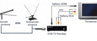
So, if you decide to organize digital terrestrial TV channels, you will need: A TV with a built-in DVB-T2 tuner or, if you don’t have one, then you will need a set-top box for digital television, also in DVB-T2 format. And of course the antenna itself, UHF range.
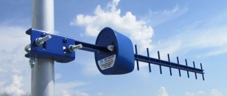
Main technical characteristics of the Polish antenna
The “Polyachka” range operates from 40 to 800 MHz. This allows you to receive signals and watch TV shows from channels 1 to 20.
With a little modification and connection of the amplifier, it also becomes possible to watch TV channels from 21 to 69. Additionally, the basic configuration of any array antenna model includes its own signal amplification of up to 13 decibels, as well as a characteristic impedance of 300 ohms.
The dimensions of the equipment are relatively small (80x60 cm), weight is 1.5 kg.
The list of antenna components upon purchase is impressive:
- active vibrators (UHF, MV);
- passive vibrators (directors);
- slats for attaching base lines of waveguides and plastic housings;
- mounting an antenna with a reflector;
- reduced voltage units;
- various amplifier models at the buyer’s choice;
- standard plugs for connection.
Coaxial cables required to connect the device to the translator are purchased separately.
How does the Polyachka TV antenna work when receiving a digital signal?
The basic kit does not imply the use of equipment to receive 10 or 20 digital TV channels distributed throughout the country. In any case, until there is an official update to the antenna from the manufacturer, you will have to improve it yourself in order to achieve the required signal level. With proper modification, the Polish array responds well to long-range digital signal reception.
There is a small percentage of probability that, due to the similar signal reception range, the antenna can partially capture the image and broadcast sound even without modification. However, the signal will be weak and difficult to detect on a permanent basis. The standard amplifier that comes with antenna arrays is also not suitable for working with digital television. It needs to be upgraded to improve signal reception quality.
A positive effect is achieved only if the antenna is located close to the repeater tower. In this case, a minimum amount of signal amplification or reduction is required to achieve a high-quality image using standard devices available in stores and electronics markets.
Remaking the antenna to receive digital broadcasting
Modern television signal receivers (TVs) from their owners require a higher quality signal than analog television; a TV antenna is needed that can pick up a DVB - T2 signal. The market is saturated with many fakes that pass off as digital TV signal receivers, for this reason experts recommend considering something like an antenna for digital television made from an existing analog antenna.
Modified analog antenna for digital
There are options when a DIY antenna for digital TV is obtained from a common “Polish” antenna. An important condition for such a conversion is that your TV has DVB-T2 support, but even in this case, you can buy a set-top box, which is cheaper than a new TV. With the presence of a television receiver and an adapter for T2, the cost of alteration will be minimal.
Do-it-yourself antenna and the necessary parameters that must be met before starting work are the location of the tower from your place of residence: the further it is, the less likely it is to receive digital broadcasting. In the version with a “Polish” antenna, the distance from the tower should not be further than 25 kilometers. What is needed for work:
- Make sure that the antenna wire is in working condition or replace it along the entire length with an RG6 cable;
- You need to buy an LSS-940 plateau and a male plug, an F connector adapter for the cable that you have;
- Prepare tools: knife, screwdriver. For these purposes, you should not spend money on a special insulation stripping tool or other electrical tools.
We carry out the work according to the following method:
- in the apartment, disconnect the power supply from the TV signal receiver;
- at the signal receiver and its subsequent amplification on the street, remove the SWA amplifier board;
- instead of the SWA amplifier we install the LSS 940 board;
- the power supply unit will no longer be needed in operation, since the matching plate installed on the antenna does not have transistor amplification stages;
- in the apartment we screw the adapter F connector onto the antenna wire, first you need to cut the cable correctly with a 100% guarantee of the integrity of the main core and full contact of the screen with the outer part of the connector;
- We put the “male” plug on the connector;
- if you have a set-top box, plug the plug into it; if it is a supported built-in adapter, plug the plug into the TV;
- using automatic tuning of television channels, we find multiplex first and second;
- As a result, 20 digital broadcast channels and up to 3 radio stations should be received.
Important! A digital broadcast signal has its own peculiarity: it either exists or it doesn’t. Unlike analogue broadcasting, when signal amplification is required and there is the possibility of interference, in digital broadcasting the signal strength on all television channels is the same, if there is one, all channels will show it.
The array antenna, popularly called “Polish,” has its drawbacks, the main one being a violation of trade rules. This happens when the buyer is promised a guarantee of up to six months, but despite the fact that it applies to the entire set, there are various excuses and reasons not to fulfill it, namely:
- the presence of scratches on the signal amplifier, which breaks down most often, the presence of non-standard stickers on the board;
- the antenna is not fully equipped for return;
- the presence of protective means against moisture penetration on the amplifier plateau (waterproof paint, glue, varnish);
- The warranty may not indicate the release date of the product.
Even with all the shortcomings, if used correctly, since this is also a technique that requires attention and maintenance at least once every two years (checking contacts, connections, reliability of shelter from moisture), this type of antenna can work for a long time and effectively.
Selecting an amplifier for a Polish array for long-distance reception of a DVB-T2 signal
Without an amplifier, the Polish array will not be able to receive and process incoming new generation signals. The base amplifier in the pole antenna is produced separately. In radio electronics stores it can be purchased for no more than 200 rubles.
When choosing an amplifier, it all depends on what signal range the user needs to use for reception. Each radio element of a standard amplifier is fixed using a hinged method to the main part of the antenna. It is there, in the central part of the equipment, that a small secure box is located. Through the board installed in it, you can improve the signal reception effect.
The main task of digital antenna amplifiers is to improve the quality of incoming television signals. Any of the models on the market amplifies received broadcast signals equally well - their quality depends on the distance from the main repeater.
To select a specific amplifier model, depending on the power and distance from the TV tower, you can use the following table:
| Amplifier types | Applicable gain level in dB | Produced noise from the amplifier in dB | Distance from the tower broadcasting the signal, km | |
| Reception of channels from 1 to 21 | Reception of channels from 21 to 68 | |||
| SWA 1 and Lux | 2-14 | 8-23 | up to 2.8 | 3-15 |
| SWA 2 | 15-18,5 | 20-25 | up to 2.8 | 10-20 |
| SWA 3 | 2-6 | 20,5-28 | up to 3.1 | 10-30 |
| SWA 4 Lux | 0-8 | 29-35 | up to 3.0 | 20-45 |
| SWA 5,6,7 | 5-17 | 25-38 | from 1 to 3.9 | 10-70 |
| SWA from 9 to 65 | 9-20 | 21-43 | from 1.9 to 3.1 | 30-100 |
| SWA 555 Lux | 10-15 | 34-43 | 2,2 | 50-100 |
| SWA 777 Lux | 10-13 | 34-45 | 2,3 | 50-100 |
| SWA from 999 to 9999 | 0-52 | 10-54 | from 1.2 to 2.9 | 20-150 |
In stores and on the radio market you can find a large number of translators for the Polish antenna. There are dozens of models available for customers to choose from. They all have the same dimensions, but differ in reception quality and signal strength from 30 to 48 decibels.
All amplifier boards, including those for receiving a digital signal, have a voltage of 12 volts, which they receive from reduced voltage supply units 220 to 12 volts. All incoming voltage that goes to the main board located on the antenna passes through a special plug that has a built-in capacitor. With its help, there is a separation between power and incoming signal.
When choosing the right type of amplifier for your array antenna, you can ask your neighbors or see what model they have installed on their roof. Using the table, you can calculate the approximate level of the digital signal that will reach your equipment.
Antenna amplifiers SWA
In the article published here, our regular author analyzes the circuitry of Polish-made antenna amplifiers and justifies his informed approach to their selection in terms of noise and gain factors. He also gives recommendations for repairing such devices, which quite often fail from lightning discharges, and eliminating self-excitation. This will hopefully allow many radio amateurs not only to choose the necessary amplifier, but also to improve its performance.
Active antennas from the Polish company ANPREL and some others have become widespread in Russia and the CIS countries. With insignificant self-gain, especially in the MB range, the parameters of such an antenna are largely determined by the antenna amplifier installed on it. This particular block is characterized by a number of disadvantages: it is prone to self-excitation, has a fairly high level of its own noise, is easily overloaded by powerful signals of the MB range, and is often damaged by lightning discharges. These problems are familiar to many owners of such antennas.
The issues of operating antenna amplifiers SWA and similar ones are extremely poorly covered in the literature. We can only note publication [1], which indicates that the amplifier is overloaded with MB signals. Antenna owners have to deal with other shortcomings in a well-known way: by replacing amplifiers, choosing the best one. However, this method requires a lot of time and effort, since the amplifier is usually difficult to access - it is located along with the antenna on a high mast.
Based on an analysis of circuit design, my own experience and some materials from ANPREL, I propose a more informed approach to the selection of amplifiers, as well as a repair method that allows you to restore a damaged unit, and in some cases, improve its parameters.
The market is filled with many interchangeable models of antenna amplifiers produced by ANPREL, TELTAD and others under different brands and numbers. Despite this diversity, most of them are assembled according to a standard circuit and are a two-stage aperiodic amplifier based on microwave bipolar transistors connected according to an OE circuit. To confirm this, let's look at models from different companies: a simple amplifier SWA-36 from TELTAD, the circuit diagram of which is shown in Fig. 1, and the common amplifier SWA-49 (analogous to SWA-9) from ANPREL - Fig. 2.
Fig.1-2
The SWA-36 amplifier contains two broadband amplification stages based on transistors VT1 and VT2. The signal from the antenna, through a matching transformer (not shown in the diagram) and capacitor C1, goes to the base of transistor VT1, connected according to the OE circuit. The operating point of the transistor is set by the bias voltage determined by resistor R1. The negative voltage feedback (NFF) operating in this case linearizes the characteristic of the first stage, stabilizes the position of the operating point, but slightly reduces its gain. There is no frequency correction in the first stage.
The second stage is also made on a transistor according to the circuit with OE and with voltage feedback through resistors R2 and R3, but also has a current feedback through resistor R4 in the emitter circuit, which rigidly stabilizes the mode of transistor VT2. To avoid a large loss of gain, resistor R4 is shunted to alternating current by capacitor SZ, the capacitance of which is chosen to be relatively small (10 pF). As a result, at the lower frequencies of the range, the capacitance of the SZ capacitor turns out to be significant and the resulting negative feedback on alternating current reduces the gain, thereby correcting the frequency response of the amplifier.
The disadvantages of the SWA-36 amplifier include passive losses in the output circuit on resistor R5, which is connected so that both the constant supply voltage and the signal voltage drop across it.
The SWA-49 amplifier is built similarly (Fig. 2), which also has two stages assembled according to a circuit with an OE. It differs from the SWA-36 in better isolation of the power supply circuits through L-shaped filters L1C6, R5C4 and an increased gain due to the presence of capacitor C5 in the OOS circuit (R3C5R6) of the second stage and transition capacitor C7 at the output.
Similar circuitry is inherent in most other SWA amplifiers (see, for example, the SWA-3 amplifier circuit shown in [1]). Minor differences are most often found in the second stage, which can be equipped with different frequency correction circuits, have different OOS depth and, accordingly, gain. For some models, for example SWA-7, the first and second stages have a direct connection - the collector output of transistor VT1 is connected directly to the base output of transistor VT2. This allows both stages to be covered by the DC feedback loop and thereby improves the thermal stability of the amplifier.
In cascades based on transistors connected according to a circuit with an OE, the influence of internal connections and transition capacitances of transistors is greatest. It manifests itself in the limitation of the bandwidth and the tendency of the amplifier to self-excitation, the probability of which is greater, the higher the gain. To evaluate it, the concept of stability threshold is known - the limiting value of the gain, above which the amplifier turns into a generator. Many high-gain SWA antenna amplifiers operate near the stability threshold, which explains their frequent self-excitation.
As measures to increase the stability of amplifiers, ANPREL uses different topologies of printed circuit boards (affecting the mounting capacity), surface and volume coils, chokes, etc. A more radical method: switching transistors in a cascode circuit with OE-OB - for some reason not used . With an unchanged switching circuit for transistors with OE-OE, to solve the problem of stability, the company prefers to produce regulated power supplies. By reducing its voltage, it is possible to eliminate self-excitation of the amplifier while maintaining sufficient gain.
The main parameters (noise figure Ksh and gain Ku) of the basic models of SWA amplifiers according to the ANPREL catalog are listed in table. 1.
Let's consider the relationship of the main parameters with the circuitry of amplifiers and their impact on the reception quality.
As is known, the gain at high frequencies in cascades with OE is critical to the parameters of the transistors used, especially to the cutoff frequency frp. SWA amplifiers use bipolar microwave transistors of the p-p-p structure, labeled as T-67, less often - 415, which determine the maximum achievable gain Ku of a two-stage amplifier of about 40 dB. Of course, in such a wide operating frequency band, the gain does not remain constant - its changes reach 10... 15 dB due to uneven frequency response at higher frequencies of the range and correction at lower frequencies. At maximum values of the gain Ku it is difficult to ensure the stability of the amplifiers, therefore in a number of models it is limited to values of up to 10...30 dB, which in many cases is quite sufficient (see Table 1).
Contrary to popular belief, it should be noted that gain cannot be considered the main parameter of an antenna amplifier. After all, the TVs themselves have a very large reserve of their own gain, i.e. They have high sensitivity, limited by gain. Their sensitivity, limited by synchronization, is somewhat worse. And finally, the lowest is sensitivity limited by noise [2]. Consequently, the factor determining long-range reception should be the level of intrinsic noise of the electronic path, and not the gain. In other words, the limitation of reception is primarily due to the influence of noise interference, and not due to a lack of signal amplification.
The influence of noise is assessed by the signal-to-noise ratio, the minimum value of which is taken to be 20 [2]. With this ratio, noise-limited sensitivity is determined, which is equal to the input signal voltage 20 times greater than the noise voltage.
For TVs of the third to fifth generations, the sensitivity limited by noise is 50... 100 µV. However, at a signal-to-noise ratio of 20, image quality is very poor and only large details are legible. To obtain a good quality image, you should apply a useful signal to the TV input that is approximately 5 times larger, i.e., provide a signal-to-noise ratio of about 100 [2].
An antenna amplifier must increase the signal-to-noise ratio, and to do this it should amplify the signal, not the noise. But any electronic amplifier inevitably has its own noise, which increases along with the useful signal and worsens the signal-to-noise ratio. Therefore, the most important parameter of the antenna amplifier should be considered its noise figure Ksh. If it is not low enough, then increasing the gain is useless, since both signal and noise are amplified equally and their ratio does not improve. As a result, even with a sufficient signal level at the antenna input of the TV, the image will be affected by intense noise interference (the well-known “snow”).
For a unified assessment of the noise of a multi-stage path, there is an indicator of the noise figure Ksh reduced to the input, which is equal to the noise level at the output divided by the total gain, i.e. Ksh = Ksh.out/Ku. Since the output noise level Ksh.out depends to the greatest extent on the noise level of the first transistor, amplified by all subsequent stages, the noise of the remaining stages can be neglected. Then Ksh.out = Ksh1Ku, where Ksh is the noise factor of the first transistor. Consequently, we obtain Ksh = Ksh1, i.e. the reduced noise figure of the amplification path does not depend on the number of stages and the overall gain, but is equal only to the noise figure of the first transistor.
This leads to an important practical conclusion - the use of an antenna amplifier can give a positive result when the noise figure of the first transistor of the amplifier is less than the noise figure of the first stage of the TV. The channel selectors of fifth-generation TVs use the KP327A field-effect transistor with a noise figure of 4.5 dB at a frequency of 800 MHz [Z]. Therefore, in the first stage of the antenna amplifier a transistor with Ksh1<4.5 dB should operate at the same frequency. Moreover, the lower this value is compared to the Ksh1 coefficient of the TV, the more effective the use of the amplifier and the higher the quality of reception.
The noise figure also depends on the quality of matching at the amplifier input and the operating mode of the first transistor. For SWA amplifiers, the type of transistor VT1, its operating mode and the quality of matching determine the reduced coefficient Ksh = 1.7...3.1 dB (see Table 1).
From the above it is clear that choosing an antenna amplifier according to the principle - the higher the gain, the better - is incorrect. This is why many owners, when changing amplifiers, cannot achieve good results. The reason for this paradoxical, at first glance, fact is that the noise figure is, as a rule, unknown (it is not in the sales information of companies), and in fact it only differs slightly for many models with different amplifications (see Table 1 ). Increasing the gain with a constant noise figure does not provide a gain in the signal-to-noise ratio and, therefore, does not improve the quality of reception. A rare success is achieved only when a low noise amplifier comes across by chance.
Therefore, when choosing an antenna amplifier, you need to focus primarily on the minimum noise level. An amplifier with Ksh<2 dB can be considered quite good. From the table 1, the best models can be considered SWA-7, SWA-9, having Ksh = 1.7 dB. Information on the noise figure of new amplifiers can be found in ANPREL catalogs or on the Internet.
As for the gain, it, of course, also matters, but not for maximum amplification of weak signals, but, first of all, to compensate for losses in the connecting cable, matching-branching devices, etc. Because of these losses If there is insufficient amplification, the signal level at the TV input may fall below the sensitivity threshold, limited by synchronization or even gain, making reception impossible. Therefore, to correctly select the gain, it is necessary to know the signal attenuation in the entire connecting path. And its approximate value is easy to calculate.
The linear attenuation of the signal in the common RK-75-4-11 cable is equal to 0.07 dB/m at the first to fifth, 0.13 dB/m at the sixth to twelfth and 0.25...0.37 dB/m at 21-60 th television channels [2]. With a feeder length of 50 m, the attenuation on channels 21-60 will be 12.5...17.5 dB. If an industrial passive splitter is installed, it introduces additional losses at each of its outputs, the value of which is usually indicated on the housing.
By calculating the attenuation in the cable and adding to it the attenuation in the splitter (if there is one), the minimum gain of the antenna amplifier is obtained. A margin of 12...14 dB is added to it to amplify weak signals, which is necessary due to the low efficiency of broadband small-sized receiving antennas. Based on the obtained Ku value, the antenna amplifier is selected. The obtained gain value should not be much exceeded, as this increases the likelihood of self-excitation and overload of nearby stations with powerful signals.
Repair of antenna amplifiers mainly comes down to replacing active elements damaged by lightning discharges. It should be noted that the presence of a diode at the input in some models does not guarantee complete lightning protection: during a powerful atmospheric discharge, both the protective diode and, as a rule, both transistors break through.
SWA antenna amplifiers are assembled using automatic surface assembly technology using microelements, which requires care during repairs. Soldering should be done with a small-sized soldering iron with a sharp tip. With the amplifier not working, you should carefully, trying not to damage the thin printed conductors, remove microtransistors VT1, VT2 and the protective diode (if any).
The main parameters of domestic transistors suitable for installation in SWA amplifiers are listed in table. 2 [Z]. It follows from it that the use of transistors KT391A-2, KT3101A-2, KT3115A-2, KT3115B-2, KT3115V-2 in the first stage does not worsen the noise characteristics of most amplifier models, and the use of transistors 2T3124A-2, 2T3124B-2, 2T3124V- 2, KT3132A-2 reduces Ksh to 1.5 dB, which improves the amplifier parameters. This circumstance allows us to recommend replacing the first transistor of the amplifier with the last ones indicated, even in serviceable but “noisy” amplifiers in order to improve the quality of their operation. It should be noted that in table. 2 gives the limit values, but typical parameters are, as a rule, better [3].
Low-noise microwave transistors of the 2T3124, KT3132 series are relatively expensive and low-current, so it is better to install them only in the first stage, and in the second use cheaper and more powerful transistors KT391A-2, KT3101A-2 (see Table 2) and even the KT371, KT372 series , KT382, KT399 and others with a cutoff frequency of about 2 GHz [Z]. However, in the latter case, the gain at the upper frequencies of the range will be slightly lower.
The housing dimensions of imported microtransistors are 1.2x2.8 mm with a lead length of 1...1.5 mm. Accordingly, the distances on the board between the printed pads for the transistor outputs are small. Installation of domestic transistors with a case diameter of 2 mm on the surface-mount side, although possible, is difficult: they can be damaged when soldering. It is better to install new transistors on the opposite side of the board, having previously drilled holes for the leads with a drill with a diameter of 0.5...0.8 mm. It is better to drill not in the printed conductor itself, but so that the hole touches the edge of the pad. If there is a layer of foil on the side opposite the surface mounting, then the holes in it should be countersunk with a drill with a diameter of 2...2.5 mm (except for the hole for outputting the emitter of transistor VT1).
Then new transistors are installed so that the crystal holder or device body touches the board. If the leads protrude significantly from the other side, they should be bitten off after soldering. Microwave transistors are sensitive to static electricity, so appropriate protective measures should be taken when soldering. Soldering time - no more than 3 s [Z].
The protective diode does not need to be installed. The best protection against atmospheric electricity is good grounding of the antenna.
In SWA amplifiers, both transistors operate with a collector current of 10...12 mA. After replacement, such a current is acceptable for the second transistor (for example, KT3101A-2), but exceeds the permanently acceptable one for the first if transistors of the KT3115, KT3124 and KT3132A-2 series are installed (see Table 2). The collector current depends on the parameter h21e, according to which the transistors have a significant spread. Therefore, after installing a specific instance, it is necessary to set the operating point of transistor VT1. To do this, remove microresistor R1 and temporarily connect a tuning resistor (SPZ-23, SPZ-27, etc.) with a resistance of 68...100 kOhm instead. Before turning on the power, the resistor slider must be in the position of maximum resistance so as not to damage the transistor.
The amplifier is supplied with a voltage of 12 8 from the power supply and the voltage drop across resistor R2 is measured (see Fig. 1 and 2). By dividing the measured voltage by the resistance of resistor R2, the collector current is determined. By adjusting the resistance of the tuning resistor towards a decrease, a collector current of about 5 mA is achieved, which corresponds to the minimum noise according to the characteristics of the transistors [3]. At this point, the adjustment is completed and instead of a tuning resistor, a constant of the same resistance (MLT-0.125 or imported) is soldered in, having first shortened its terminals to a minimum.
After this, the printed circuit board and unpackaged transistors are covered with a layer of radio engineering varnish or compound. The appearance of the restored SWA-36 amplifier is shown in Fig. 3. It uses transistors (Fig. 3,a) 2T3124B-2 (VT1) and KT3101A-2 (VT2). Due to the simplest design of the amplifier, measures have been taken to eliminate self-excitation: a ferrite microring is placed on the collector terminal of transistor VT1 (it is used in the SK-M channel selectors of ZUSTST and 4USTST TVs). The collector current of transistor VT1 is set by resistor R1 (Fig. 3.6) with a nominal value of 51 kOhm (was 33 kOhm).
Fig.3
In the second stage, transistors of the KT372, KT399 series were tested, with which stability and sufficient gain were maintained. At the same time, the possibility of installing an additional capacitor CD with a capacity of 150 pF (Fig. 3.6), shunting resistor R5 (see Fig. 1), to increase the gain was tested. When installing a capacitor, self-excitation of the amplifier is eliminated by lowering the supply voltage.
In the basic version (with transistors 2T3124B-2 and KT3101A-2), the amplifier provided better reception quality than before the repair, which was visually assessed to be approximately the same as reception with the new SWA-9 amplifier.
LITERATURE: 1. Tuzhilin S. Broadband UHF amplifier. - Radio, 1997, N 7, p. 15. 2. Nikitin V. Advice for fans of long-distance television reception. Collection: “To help the radio amateur”, vol. 103. - M.: DOSAAF, 1989. 3. Semiconductor devices. Low power transistors. Directory. Ed. A. V. Golomedova. - M.: Radio and Communications, 1989.
Radio 1-99
Tags:
- Antenna
Possible problems when trying to receive digital TV using the Polish grid
Normally working Polish antennas with an amplifier and power supply may experience the following malfunctions:
- the signal begins to disappear completely;
- when setting up digital television broadcasting, the scale displaying the signal level begins to quickly increase to 100 or, conversely, drops to 0;
- At first there is a reception, but over time it begins to weaken or disappear completely;
- the image begins to slow down, cubes appear, the sound begins to stutter;
- of the 20 channels available for free broadcasting, only 10 are shown - and even then with poor images;
- If the antenna is located at a low height of 2.5-3 meters, then cars passing by it on the road can cause the signal to start to malfunction.
All this leads to the need for modifications to improve the quality of reception and prevent various kinds of problems.
If you are tuning into a digital broadcast and see the level meter rise and fall rapidly, it is being lost. In other words, such a digital signal through the “Pole” is unsuitable for decoding. In this case, modification of the equipment will be required.
How to get rid of signal skew
The skew of the received signal, as mentioned above, occurs due to the difference in the power of the signals transmitted from the TV tower. There are several ways to get out of this situation, these are:
- The Polish antenna with amplifier SBA 9000 allows, using adjustment resistors in the circuit, to adjust the gain separately on the (MV) range and (UHF) range, finding the optimal solution. It is considered the most effective way;
- The best method for ease of implementation is when the “antennae” of the active upper vibrators, responsible for the (MV) range, are connected, removed or bent. By this we achieve a reduction in the received signal, which is better - selected individually;
- There are two types of power supply units on sale - one with voltage regulation and one without a regulator, when it reaches a stable plateau of 12 volts. By changing the supply voltage, you can achieve the optimal level of signal amplification in the (MV) range.
Important! Experts recommend paying attention to the first and third methods, which are used together to achieve excellent results.
There will be a good signal when the amplifier and power supply work together, but this device for receiving and amplifying the signal from a TV tower has the option of working without a power supply and amplifier.
What to do if the Polish network does not accept DVB T2?
If “Pole” does not receive DVB T2 and does not respond in any way to manual settings, this cannot be the TV’s fault. Many users believe that the basic gain found in modern plasma and LCD devices is sufficient to access digital broadcast levels. According to many sellers, modern TVs have the ability to receive a signal without connecting antennas. However, in practice it turns out that the further a person is from the signal repeater, the worse the reception becomes.
This state of affairs is especially noticeable in remote areas of the country, which recently switched to digital television broadcasting. Repeater towers have to add amplification so that local residents can achieve the same quality as channels in urban areas.
In many cases, the cause of a poor signal when receiving DVB-T2 is increased power. An incorrectly selected translator can significantly increase outgoing performance, which will lead to interference. There are four ways to correct this problem and achieve better digital TV reception.
In a previous article on this topic, I wrote about why this antenna may not work, namely:
- How its problems manifest themselves
- Why does this happen
- How to eliminate them without removing the antenna - 5 ways
MOTTO: Every TV viewer has the antenna that suits him!!!
My acquaintance with this “mysterious” antenna happened a long time ago, somewhere at the beginning of “perestroika,” when there was still no alternative or competition in offering buyers more worthy options for television antennas.
Having bought this copy of a foreign miracle, I was surprised at how simple and easy it was to make. Karl Rothhammel is on vacation with all the Eisenbergs. Having installed it above the roof of my parents’ private house, we enjoyed a pretty good image of the old Record for some time.
But, as they say, the music did not play for long. It seemed that the passing thunderstorm had left only wet grass and wind-blown apples in it, but that was not the case. The thunderstorm passed, leaving a double image and only two channels - the first and one of the UHF channels on our TV. Realizing that the amplifier on the antenna was out of order, I went back to the store.
Having given fifty of his hard earned money and climbed upstairs, he placed the amplifier in its rightful place. Soon everything happened all over again and these voyages began to bother me. From my friends I learned about the need to ground the reflector grid, but this did not help for long.
Just two years later, the structure began to collapse due to low-quality plastic used to make the fastenings of the fan vibrators to the connecting line. I had to sell the poor thing for two glasses of cold compote on a hot day, I think this was its red price.
Learning more and more about its “advantages,” I set up an experiment that lasted about five years. Having made the purchase of another (Polish antenna), I experimented for a long time with the power of my transmitter, the ranges of short and ultra-short waves, transmitting antennas, filters, and finally realized that this creature receives whatever it wants and indiscriminately.
Even a milliwatt power from a verified signal, the G4-116 generator, was enough for so-called “interference” to appear on the TV screen.
At the same time, our shortwave brethren assigned it various funny nicknames: “Polish antenna”, “back wall of the refrigerator”, “sabotage”, “garbage bin”, “dryer” and so on.
I think and know that homemade antennas work much better and do not require frequent repairs for years. Looking at the documents that were with my ward, I did not find either GOST, or the country of manufacture, or the enterprise responsible for its products. Something had to be done with the antenna! From scattered articles and communicating on the air with other radio amateurs, I learned about the need to exclude the SWA-... amplifier from the antenna.
The antenna on the side of the collecting line has an input impedance of about 300 Ohms (depending on the integrity of the unknown manufacturer), then there is a 4:1 matching transformer (usually binocular type), an amplifier and a cable with a resistance of 75 Ohms.
By removing the amplifier, we get a simple, understandable and more reliable antenna system. Taking a scalpel or a small sharp knife, we mercilessly cut off (clean off) all the planar mounting elements on the printed circuit board of the SWA -... amplifier, leaving only the matching transformer.
Then we solder a short piece of wire such as PEL, PEV, PETV with a diameter of 0.35 - 0.5 mm. between the transformer output and the cable and that’s it, gentlemen!
At one time, I converted more than a dozen “amplifiers” in this way for little money (you have to pay for the idea and work). There were no dissatisfied people!
I draw your precious attention to the fact that it is advisable to carry out this modification with unusable amplifiers, but if there are none...
An unknown antenna of an unknown name from an unknown manufacturer converted in this way, which does not comply with any GOST, works quite well and is little sensitive to the radio frequency fields of all kinds of radio services induced on it.
It is useful to make several of these boards from unusable ones and not waste money on buying a “more powerful” amplifier. I would like to touch on one more disadvantage of the “unknown” antenna: this is the universal self-excitation of amplifiers. The next time they fail, they begin to emit an unstable carrier modulated by the background into the air (the signal is like from a transmitter).
When heated by the sun's rays, and in winter at sub-zero temperatures and wind, the frequency of this signal begins to float or wander, and if you take into account its flimsy design, uncontrolled jumps, leaps, etc. are possible. I have repeatedly observed interference from such antennas in the area of the 5th frequency channel - stripes, ripples and a hoarse sound until it disappears completely.
This effect was also observed by other television viewers, of course blaming the unfortunate radio amateurs. The interference radius is approximately 30 - 40 meters; it can also spread through the wires of the lighting network from one TV to another.
The gain of “branded” amplifiers reaches 40 decibels or more! When coming to the store for another purchase, the buyer is usually offered a more “powerful amplifier” (hee). Probably with such capabilities it is possible to receive signals from some satellite located in the orbit of Pluto (chi).
Once passing by one of the houses and looking at its floors, I counted 38! ! ! similar antennas. You can imagine how good life is for them there. Some emit interference, others amplify it to extreme levels (fun, right?).
There is only one thing that pleases us - GOSSVYAZNADZOR, during a conflict with neighbors, regarding alleged interference from shortwave, upon seeing the “back wall of the refrigerator”, they immediately write an order to connect the TV to the collective antenna.
As usual, when contacting the happy owner of the “antenna”, there is a statement that everything is fine with him. However, when watching the programs, it turns out that he watches one or two channels, and even then with poor quality. If you try to explain everything that is happening to such a “woe-to-be TV viewer” and ask to replace it with a high-quality certified antenna, then most often you get a refusal!
From here I draw my conclusion:
1. The antenna is poor due to its unreliable design 2. Lack of necessary interference filtering 3. The antenna amplifier does not provide protection against input overloads 4. The materials used are susceptible to corrosion and destruction from ultraviolet radiation of the sun 5. Non-compliance with GOST 6. Lack of company indication - manufacturer 7. Lack of warranty 8. Lack of name!
(PS)
Since this article aroused great interest among readers who were clearly not radio amateurs, I decided to write a continuation of it about which antennas and how they should and can be installed and operated.
Due to the fact that, despite our education, we still remain quite dark and unenlightened in many matters. That’s why I decided to share in this article about some of the secrets and highlights of “antenna construction”.
Personally, I have a huge request: do not buy “Polish antennas”, as well as creations similar to them. to the sellers’ assurances “this antenna is in great demand!>”!
This is a trick of traders as old as the world, and it’s time to learn not to step on the same rake twice or thrice. Unfortunately, we all have one disease - short memory. And for example, every 7 - 8 years you can organize “JSC MMM”.
Personally, I was pleased with this fact: “Polish dryers” began to appear near garbage cans (finally they began to see the light!) and, unfortunately, there are those who... pick it up. Good for non-ferrous metal, but what if they put it on the roof again?
For radio amateurs: to fix the 145 MHz problem. A quarter-wave piece of cable, tuned to the frequency of the two-meter range, connected between the antenna and the amplifier, parallel to the amplifier input, helps. According to information from other sites, it also cuts off 435 MHz. at the third harmonic.
A more complete solution to the “dryer” problem is offered by REMO LTD from the glorious city of Saratov. According to their assurances, amplifiers have appeared on sale that can replace the “Polish” SWA series. Although, to be honest, I don’t understand why amplifiers are needed if the television center is 10-15 km away.
It is only necessary to ensure direct visibility to the television center, and amplifying reflections and re-reflections from the basement or balconies is a thankless task. They also offer a set of ANTI - TV1 filters for television antennas.
In general, the procedure for planning and installing TV antennas should be as follows:
1. You need to know what you are going to receive (which channels) 2. Conduct reconnaissance on the ground (visibility of the transmitting TV center, cable length, etc.) 3. Assess your finances (maybe you should connect to cable TV or buy a dish? )
Based on this, let's take the most common and simple example: there is visibility from the roof of your apartment building and all the TV companies have hung their transmitting antennas on this one mast.
We proceed as follows: we simply buy an all-wave antenna, for example “Delta”. Next, if one channel is weak, we orient the antenna along it until the best image is obtained.
If this is not achievable, you can either accept it or play with the height of the antenna.
ATTENTION! The installation height of the TV antenna should not be less than 3 meters. This is due to the wavelength of the first frequency channel - 6 meters (not to be confused with the button on the remote control). By installing your antenna low or close to other hardware, you significantly worsen the operating conditions of the antenna.
If this does not help, then you can already use an amplifier with a characteristic that has maximum gain in this area (the region of this channel). But not the SWA type. You can consult with specialists or with the same radio amateurs, since they have the necessary information (obliged).
We can stop here, but if you want more, then we’ll continue. As you know, TV channels are divided into three subranges: 1 - 5; 6 - 12; 21 - 60. Hence we plan three antennas:
1. The first for the range 1 - 5 channel with a low gain (2 - 3 element) 2. The second for the range 6 - 12 channel with an average gain (3 - 6 element) 3. The third for the range 21 - 60 channel with high gain (5 - 10 elements)
All these antennas do not need to have active amplifiers. I'll explain why. The cables from these three antennas are connected there at the antennas (on the roof); there is no need to lower them down. They are connected together using “splitters”, of which there are now many in stores and for any choice.
Since these devices have different circuitry, current may not pass through it to the amplifier, shorting through a coil or resistor. The consequences can be disastrous not only for you, but also for the general roof (fire).
Do not choose the cheapest one - plastic, it will quickly fall apart from the sun's rays. Choose a soldered metal one with four pins for three antennas and an output cable.
Look carefully at the characteristics that are drawn on the lid or on the accompanying document. It is very desirable to have a low attenuation of the “splitter” or whatever you call it. The smaller it is, the better for you. All this is connected using the now common television connectors.
The location of the antennas in height should be as follows: at the bottom, antenna 1 - 5; above 6 - 12; upstairs 21 - 60.
And once again: ATTENTION! The installation height of the TV antenna should not be less than 3 meters. Here we mean the distance from the roof itself to the antenna of 1 - 5 channels.
Look at the old-style collective television antennas: they are installed on masts 3.5 - 5 meters high. This is a role model. The distance between the “floors” of antennas should not be small, from 1.5 meters and a little more.
Now about choosing a cable. We need a good cable. Nowadays, RG type import cable is very common - there are 6 different modifications. Domestic cables like RK - 75... are also common, but quite expensive.
Let's consider which is better. Cables of type RK - 75... have a good thick braid of copper, at least such should be used, and polyethylene as an insulator between the central core and the braid. Yes, good cable, solid design, but high price.
RG - 6 has aluminum foil and several braided hairs. Foamed polyethylene is used as an insulator. The design of RG-6 is fragile, foamed polyethylene “sucks” moisture and cannot be bent at an acute angle, since the aluminum foil may burst and then the cable will be completely damaged.
But because of this very foamed polyethylene, the losses at high frequencies are small, small compared to simple polyethylene of the domestic cable. Therefore, I would recommend using imported RG-6 cable, but with the above precautions.
If the cable is long, it is necessary to use galvanized wire with a diameter of 2 - 3 mm. and securely fixed at the two points you need. The cable is attached to it using aluminum strips or imported electrical tape (this is worse).
And further. If you come across a 75 ohm cable with a large diameter of 10 -11 mm. and semi-air insulation, then you are lucky! You are very lucky, buy without hesitation. Such a cable has very low losses and is suitable for your “reduction” needs.
Now, if you build such an antenna system, then you will have a decent TV signal at the TV input and it will be quite possible to even sell this signal to your neighbors or divide it between several of your TVs.
Regarding the “official” installation of antennas, I would like to say a few words. Some people may not know, but quite good laws have been in place for many years. For example, the Civil Code of the Russian Federation, articles No. 289 - 290, and the Housing Code, article No. 36.
But employees of housing and communal services do their best to prevent citizens from using their property. Since, according to the law (Code), any brick or pipe in your residential building belongs to you and other residents on the basis of shared ownership, demand a key to the roof, and do not ask.
Management organizations only manage repairs in your home. Actually, we pay them money for this, since we got them the job!
If they refer to some kind of resolution, look: it is not a law, and if it prevents you from receiving information from the air, then this is already a violation of the article of the Constitution of the Russian Federation on the freedom to disseminate and receive information, as well as infringement of the rights of television broadcast consumers.
It turns out like in the song by V.S. Vysotsky: “and then the head physician Morgulis banned television.” Whatever happens to us, like in that madhouse, we need to fight through the court and the housing office and the service company. And the more often we do this, the more order we will have in our country.
And regarding the “Polish dryers”, the following can be said in conclusion: the production, distribution, sale and import from abroad of such low-quality products must be prohibited, since they do not meet any standards here in the Russian Federation, much less abroad. If you search the Internet for information about “Polish antennas”, you can find a lot of negativity.
Here are just a few links with information on this matter:
* https://www.qrz.ru/schemes/detail/2796.html * https://www.pro-radio.ru/video/43-2/ * https://rumlin.narod.ru/pol_ant. html * https://mindmix.ru/tv/35-100-chto-mozhno-sdelat-s-pol-skoi-antennanoi-quot-setkoi-quot-read.shtml * https://www.g-2b. com/ur5ufq/polka/index.html * https://www.forum.cqham.ru/viewtopic.php?p=103583 * https://www.desna.com.ua/Publikacii/ANT_POLAND.htm * https: //us4es.narod.ru/anten.html * https://www.telesputnik.ru/forum/viewtopic.php?t=23528&sid=3e10caaba228d5548702cbfedcc83b90 * https://forum.vernet.su/viewtopic.php?id= 364 * https://forum.mediaport.info/read.php?5,253213,256628,quote=1 * https://gazetazp.ru/2004/180/4/#comment * https://connubialcon.mail333 .su/istochnik_pomeh_polskaya_antenna.html * https://tv.net.ua/print.php?id=4653 * https://www.rfc24.ikr.ru/index.files/Page961.htm * https://www .cableman.ru/forum/viewtopic.php?t=2293&sid=8110e4ae6a8008f693d18e9ddade2919 * https://www.stvnn.ru/efir%20tv/statia2.htm Author: Valery UA4CGR
Related materials:
- Antenna for digital TV
- Antenna FO0AAA
- Fractal antennas: less is more?
- UW4HW - umbrella
- Outdoor TV antenna for 12 channels
- Tri-band WARC dipole
- Antenna RA4DX 160 meters
- A Dual Band VHF/UHF J Pole
- Multi Delta
- Universal all-wave antenna for MB and UHF bands
- Mysterious Polish antenna
- Antenna EI7BA for low frequency ranges
- MoxGen Program
- Antenna - Cut Square
- Antenna Double Bazooka
- Antenna DX 2000
- Such a different Windom antenna
- Vertical for hiking
- Radio antenna RX3AKT
- Antennas and accessories
Making the antenna passive - Method No. 1
This method gives excellent results in the area of a good DVB-T2 signal. For example, from a TV tower in my area, at a distance of 25-30 km in line of sight, it catches perfectly.
In addition, the most problematic areas of the array antenna are immediately removed - the amplifier and power supply.
They are simply not needed!
We only need to do two steps!
- We put a regular plug on the cable. No power supply needed!
- We connect the cable to the antenna bypassing the amplifier, as shown in the photo
As you can see, the cable is attached directly to the antenna elements.
The amplifier board can be removed, but it can also be left in place; it makes it easier to secure the cable.
The plug must be installed as usual. The long whiskers of the antenna can be cut/broken off to the size of the short whiskers, so they will work in the desired UHF range.
Yes Yes!
I know! Now they will start criticizing me. They say this is unacceptable!
This goes against all the laws of radio engineering! This deprives the antenna of the necessary matching, and so on. Yes! I know! Well, to hell with them, with these laws. I also know that it works. 100%
Well, if you want to do it according to the rules, with approval, then here’s method number two!
Making a matching board from an amplifier for a Polish woman - Method No. 2
Of course, you can buy a matching board, ready-made, but I know that they are not always on sale. Yes, you can make it yourself, straight from the amplifier. What will you need for this? Actually the amplifier itself, maybe even a faulty one, a 3 centimeter piece of wire and a soldering iron.
Let's start remodeling
Amplifiers from array-type antennas have a balun transformer, and we will need it to match the antenna with the signal consumer.
In the photo below, the transformer is circled in yellow.
There is no need to solder it, everything is much simpler. (A similar modification can also be made in amplifiers for other types of antennas)
On the amplifier board, from the side of the radio elements, you need to remove everything unnecessary. In principle, you can brush away everything with a soldering iron! - All elements except the transformer and terminals for attaching the cable.
But if you are an esthete, then you can remove just a few elements to turn off everything unnecessary.
Namely, unsolder the capacitor at the output of the transformer (marked with a red dot) and unsolder the strapping elements in the terminal circuit to which the central core of the cable is connected (marked in orange)
Attention! In amplifiers with other numbers, the number of elements and their location may differ, but the meaning remains the same, disconnect the transformer and terminal from the amplifier circuit.
If you find it difficult to figure out which elements need to be removed, make it easier! REMOVE EVERYTHING! EXCEPT A SMALL COIL (matching transformer) AND THOSE PARTS WITH WHICH THE CABLE IS ATTACHED. I only removed what was unnecessary.
This is how I did it! (Photo below) Of course, I washed all solder joints with alcohol. how did you wash it? — Rubbed with a thin layer, you know))) Although this is not necessary.
The final stage
Using a short wire, you need to connect the free output of the transformer to the terminal for the central core of the cable.
That's it, the approval board is ready!
You can install and try. And yes! Don't forget to use a regular TV plug instead of the power supply. The one with the separator from the power supply will not work.
There is no need to supply power to the antenna with such a board.
That's all! Found the post useful? Share with friends, like, subscribe to the channel. Thank you!
How to check a TV antenna
A television antenna is a device designed for transmitting equipment. And, depending on what device is used and a certain number and quality of channels are received.
Now, in most cases, satellite dishes are used. They are equipped with a certain set of equipment: dish, cable, converter, receiver, and so on.
How to check the performance and technical potential of a television antenna? But, like any other equipment, this device can fail not only due to mechanical damage, but also if connected incorrectly. In such situations, you need to know how to check a television antenna without resorting to the services of specialists. There are a number of reasons why on TV:
- The antenna is not tuned (there is a signal strength scale, but no quality scale).
- Absence of a power circuit in the receiver-converter flow (both scales are zero, which means there is no contact).
- The converter is faulty (the signal strength may be present, but there is no quality scale).
- The memory in the receiver settings has disappeared (during a long “rest”).
First of all, you should pay attention to the TV cable.
It should be intact and without any crimps.
- If this is a private home, then you can check the resistance of both ends of the TV cable. First you need to unplug all equipment from the outlet. Then disconnect the wire from the antenna and from the TV. And in the same way, use a tester to check the braiding and the central core for short circuits. Here, the serviceability of the cable is indicated by an infinite resistance value. But, if you short-circuit the central core and braid, the multimeter should show a value close to “0”.
- If this is a multi-story building, then you will only have to check the functionality of one end of the cable (with a plug). For this, a multimeter (tester) is used to measure the resistance between the braid and the central core of the wire. A value of several tens of ohms is considered a normal value. If it is greater than or close to “0”, a break or short circuit has occurred. In this case, it is better to find out whether the neighbors have a signal and, if so, then the problem is in the junction box or in the area from it to the plug.
When the device detects a malfunction, it is necessary, first, to find the weak point of the cable. This usually occurs in places where there are sharp bends, connected sections, or where the wind sways.
If everything is fine with the TV cable, the cause of the problem should be looked for elsewhere. The most common problem is a broken antenna head (LNB) or DISEQC (switch). This is usually understandable if some TV channels suddenly stop showing.
The converter can fail due to precipitation, short circuits and sudden voltage surges. To check whether this problem is really due to a malfunction of the converter or disk, you must:
- Disconnect
- Unscrew the LNB head from the cable.
- Turn on a channel that has stopped working.
all about satellite television
- Equipment Satellite dish
- Toroidal satellite dish
- Satellite tuner - receiver
- DiSEqC switch
- Satellite converter
- C band converter
- Satellite converter feed
- Satellite dish mounting – bracket
- Multifeed
- Multiswitch
- Orthomod satellite
- CAM modules
- Satellite dish tuning device
- How satellite television works
- Selecting a satellite dish
- Installing and configuring a satellite dish yourself
- How to flash a receiver from a USB flash drive
- Null modem cable (RS232) wiring
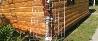
Reception of the T2 TV signal is carried out in the decimeter range and often the antennas that already exist are sufficient for this. The most common is the “Polish antenna” - a grid.
So we will upgrade it to receive T2.
Very often you don’t need to do anything and everything works well - just connect, replace the paid amplifier or throw it away altogether, and connect the cable directly or through an antenna matcher, which allows the signal to pass through the 300 ohm antenna resistance to the 75 ohm cable. and thus increases the strength of the received signal.
Although you can do without this and make a matching loop from the television cable.
In uncertain reception areas, a more scrupulous approach to antennas for receiving a television signal is needed. And for the Polish antenna a gain board is used.
But to receive T2 you do not need the entire received range that is provided for the Polish antenna. Therefore, it is better to modernize it a little and thereby increase the strength of the received signal.
As you know, such signal amplification boards are short-lived, and with a modernized Polish antenna, sometimes you can dispense with the weak link (amplification board). And thus having done it once, forget it for a long time.
Design and diagram of the crab
The TV crab is a metal box with F-connectors. Inside, on the central terminals of the connectors, parts (high-frequency transformers) of the television signal splitter are soldered. A high-frequency transformer is shaped like a ring or tube made of ferrite with a magnetic permeability of 600-2000, on which 1 to 10 turns of enameled wire with a diameter of 0.2-0.3 mm are wound, evenly spaced around the entire circumference.
- How to connect an antenna television amplifier to a power supply
In the photograph of the crab from which the back cover has been removed, you can clearly see how the ferrite transformers are wired for connecting three TVs. This crab is assembled according to the Electrical Circuit Diagram below.
All produced crabs are assembled according to the given electrical circuit diagram; there may be minor deviations - additional separating and filtering capacitors, chokes, and matching resistors are installed.
When making an adapter for supplying power to an isolated antenna amplifier, I decided not to install an additional connector for connecting the power supply, but to use one of the connectors for connecting the F-plug. To do this, we had to remove one of the transformers, limiting the crab's ability to connect only two TVs.
As a result of the modification, only two TVs can be connected to the crab, and its circuitry has changed.
All that remains is to install the LC filter in the crab and the adapter will be ready for use. Since the crab body is made of duralumin, the capacitor lead had to be connected to it through an additionally installed brass terminal, screwed to the adapter body using a screw and nut with a shaped washer.
As a result of the modification, the electrical circuit diagram of the crab acquired the following form. As can be seen from the diagram, transformer T1 remained original, but a choke and two capacitors were added.
To better match the circuit, you can solder a 150 Ohm resistor between the output pins XW2 and XW3. You can install the adapter in any convenient place, directly next to one of the TVs, or, for example, at the cable entrance to the apartment. If you need to connect only one TV, then transformer T1 can be removed, and the right terminal of capacitor C1 can be soldered directly to the central terminal of one of the connectors XW2 or XW3, to which the cable going to the TV can be connected.
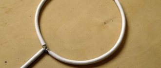
Options for converting a polished mesh to receive T2
We remove the upper vibrators of the meter range and instead put two rhombuses or bend these mustaches so that the side of the rhombus is 11 - 15 cm (selected empirically and depends on the specific reception frequency).
Reflector - we move the mesh at the back by 10 cm instead of the standard one or completely remove that part as in the figure below (preferably with a mesh).
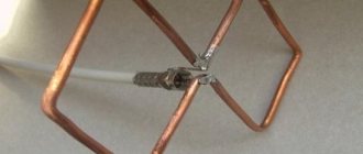
The second option for redesigning the Polish antenna for T2 reception.
We bend the vibrators as in the figure below and connect them with pieces of aluminum wire. If the vibrators are made of tubes, then the wire can be inserted into them and the edges can be crimped with pliers. For a better effect, vibrators can be shortened to 11-15cm.
And of course, it is better to move the grid back by 10cm.
As an option, replace the entire antenna with a biquad version of Kharchenko with rhombus sides of 11-15 cm in the figure below. And leave only the reflector and an amplifier if necessary.
The presence of passive directors is not necessary and there is no special result from them.
You can write your options for redesigning and modernizing the Polish antenna in the comments.
- Frequencies and channel numbers of digital terrestrial television T2 in Ukraine
- Installation and connection T2
- Repair of T2 tuners typical breakdowns
- Selecting an indoor T2 antenna
Today I want to share the secret of how to connect an antenna, popularly called “Grid” or “Pole” with digital television.
The fact is that this type of antenna does not always work stably with the new DVB-T2 broadcast format. The image may freeze at times, react to passing cars nearby, or the antenna may not work at all. What to do?
Polish antenna for digital television
With the beginning of the rapid development of television broadcasting networks in the early 90s, so-called Polish antennas became widespread. The cheapness and availability of such antennas contributed to their widespread use. However, this antenna has been widely criticized by professionals and qualified radio amateurs. Drying rack, rack, rear wall of the refrigerator. This antenna has received so many epithets. We now live in an era of widespread digital television. The question arises: is it possible to use such a frankly “under-antenna” for our show-off digital plasma. Or do you need to look for some kind of special, same fancy “digital” antenna? Let's answer this question by examining the digital model of our Polish girl...
First of all, let us immediately note the main shortcomings of this antenna, which led to such a low reputation of the Polish woman on these Internets of yours.
- An attempt to combine the incompatible and cram in the incompatible. This refers to long mustaches for receiving TV in the meter range. Since digital broadcasting is carried out exclusively in the UHF range, we can safely shorten this mustache to the size of the rest. As a result, we get an antenna array of four Butterfly antennas or fan vibrators (Bowtie). Such a vibrator has an electrical length close to the wavelength, a high input impedance, and at the same time, it is quite broadband.
- A set of directors on plastic guides has only decorative functions. Therefore, they can be safely thrown into the trash.
- The plate amplifier that comes with the antenna is prone to self-excitation. There is no input overvoltage protection; as a result, the amplifier often fails at the first thunderstorm. The tendency to self-excitation leads not only to interference on your TV, but also on the TVs of your closest neighbors. The lack of shielding and filters at the input and output of the amplifier leads to the fact that it picks up everything, including interference from car ignition systems.
- Plastic parts of the amplifier are quickly destroyed when exposed to solar ultraviolet radiation. The vibrators are attached to the collecting line using the same plastic. Over time, the contact point deteriorates as the properties of the plastic fasteners deteriorate and oxidizes. As a result, part of the “whiskers” spontaneously turns off.
A stack of four “butterflies” is quite popular among our overseas partners in the production of homemade antennas, almost more popular than the Hoverman antenna. True, they have to look for a thick wire and screw it on the knee to a wooden plank. But they are still happy and achieve good results. You and I, dear anonymous, can only sympathize with them, because we already have a ready-made inexpensive Pole. Is not it? All that remains is to make sure that the antenna has acceptable electrical parameters. To do this, we will use the Polish antenna model for the 4NEC2 program, which is available from our website.
What do we see? We see that the antenna's characteristics are rather mediocre, although in the upper part of the UHF range they can be called quite satisfactory. As the experience of overseas partners shows, using this scheme it is possible to make a quite decent antenna, only slightly larger in size compared to our Pole, but in this case, apparently, in the search for a compromise between the cheapness of the antenna and optimal characteristics, the scales tipped towards cheapness.
SWR>2 within half the UHF range. The gain throughout the entire decimeter range is 10-14 dBi, with the exception of the initial section where a dip is observed. If we take into account mismatch losses due to high SWR, then the antenna gain can be safely reduced by 2-3 dB at the beginning of the UHF range. High SWR in analog television leads to deterioration in picture quality and the appearance of noise and artifacts in the image. Digital television has its own characteristics, so a high SWR can simply lead to the inability to receive a certain multiplex, although a second one, on a different frequency, will work.
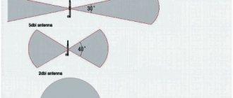
The radiation pattern is sectoral, more narrowed in the horizontal plane. Looks quite decent, i.e. The antenna has good directional properties. Among the shortcomings, it should be noted that the level of the rear and side lobes is quite large.
Having analyzed our Polish woman, we come to the conclusion that it is not we who should sympathize with our overseas partners, but they with us. After all, our Polish antenna does not have high characteristics. Of course it will work, because even a nail can be an antenna. But! No one can guarantee you the reception of all your multiplexes. There are several reasons for this. The antenna impedance varies over a very wide range with a high reactive component at certain frequencies.
This almost guarantees self-excitation of the unshielded SWA antenna amplifier that comes with the antenna. Old analog TVs had bandpass filters in the channel selectors. This somehow saved the situation. In any case, by adjusting the amplifier supply voltage, the interference could be driven outside the range and minimized. Modern digital tuners do not have such filters. There are only notch ones for the Wi-Fi frequency. As a result, powerful interference generated by the amplifier turns the input differential amplifier of the digital tuner into a nonlinear mode and reception of some or most often all multiplexes becomes impossible. In addition, in the absence of signal filtering, powerful extraneous interference may interfere with reception. Indeed, in comparison with the 90s, when the Polish antenna ruled the roost, the electromagnetic situation has deteriorated significantly. Digital data transmission networks and mobile communications have appeared, as have a large number of household appliances with switching power supplies that emit interference in a wide spectrum. All this together works against the use of a Polish antenna for receiving digital television. But you shouldn’t look for a special poncho “digital” antenna. If your Polish girl refuses to catch a number, before throwing it into a landfill and running to buy a new antenna, you should do the following:
- Shorten the top long mustache to the size of the rest;
- Throw away the plastic inserts with “directors”;
- Disassemble the points where the whiskers are attached to the collecting line and clean the contacts. Do the same at the amplifier connection point;
- Align the wires of the collecting line connecting the whiskers so that the antenna looks as “symmetrical” as possible. Align the mustache itself in the same way;
- Refuse the injector with the power supply and power the antenna amplifier directly from the TV or T2 set-top box by turning on the +5V power supply in the menu;
- Replace the old amplifier with a more modern one. Shielded, with an F-connector, with an inscription on the housing DVB-T2, powered by 5V. In this case, it is necessary to ensure that the collecting line does not touch the amplifier screen and, if necessary, insulate it;
In conclusion, we note that there are also homemade antennas optimized for digital television (including those with modifications to the Pole itself), the best of which we will present to your attention, in addition, the modernized Pole successfully works in CDMA data networks in the 800 band MHz.
Related links:
- Includes a full analysis of the more modern modification of the ASP8 antenna (poles), as well as other modifications of the “butterflies”.
- Results of using the Polish when receiving digital TV. (Remzon YouTube channel)
- .
- Kharchenko antenna optimized for digital television.
- DIY broadband wave channel for digital television;
- Features of digital television reception.
- VK()
- Comments (22)
Comments
123
#21 Sergey A. 05/27/2020 10:09 And the gain on multiplexes 650 and 778 MHz is 12 and 14 dB, that is, higher than with a double bi-square?
Quote
#22 3G-Aerial admin 05/27/2020 11:58 You can safely reduce these two figures by 1 dB (at least the analysis in HFSS shows this) and we will come to the conclusion that the difference is not significant. Higher, but no more than 1-1.5. Our decibel scale is not linear, but logarithmic. Moreover, a difference of 1-2 dB is a relatively small value. She won't do anything for you. No one is stopping you from simply checking with your hands whether the Polish fish will catch or not. You should buy the feeder anyway. The passive symmetrizer for such a test can be replaced with a half-wave loop made from a piece of feeder, designed for the average frequency between multiplexes. There is a link to the calculation in the FAQ menu. If it doesn't work, you'll have to buy an amplifier. Doesn't work with an amplifier - needs alteration or selection of an amplifier. There is no need for unnecessary troubles with decibels.
Quote
123
Update list of comments
Add a comment
Comments from anonymous people (not registered site users) are pre-moderated. Moderation does not take place in real time and there may be a delay. We ask particularly impatient anonymous people not to publish the same post in a row. In this case, the post may be rejected by the moderator. Messages from disposable and non-existent emails are also deleted. The site has a forum and comments on social networks, where there are many more opportunities for communication.
©3G-Aerial
How can the “Grid” antenna perform with digital TV?
If you live not very far from a digital television signal translator, then this type of antenna can behave rather strangely.
By default, the Polish antenna is used with an amplifier and power supply. And if, when using such an antenna, provided that all connections are made efficiently, something incomprehensible happens to the signal, for example:
- The signal is completely absent, the antenna does not pick up anything.
- During setup, the signal level scale constantly jumps from zero to one hundred. This can easily be mistaken for a bad connection. But this is not true, it's the antenna.
- There is reception, but at times the signal weakens or disappears completely. The image often “freezes” - freezes for a while, crumbles into cubes, and the sound stutters.
- Out of 20 possible channels, only 10 are shown.
- The signal disappears or weakens when cars pass nearby (if the antenna is installed low and next to the road)
All these are precisely those cases when some alterations will be required.
In my area, at a distance of 25 km from the broadcast tower, “Poles” often behave exactly like this!
Antenna operation without an amplifier
Antenna for Yota
A Polish antenna or array can work without an amplifier when you live in an area with reliable TV signal reception, when a television tower is located near you. Ferrite transformers, which are located on the matching plate in the picture, work to match the wave impedance of the device receiving the signal of 300 Ohms and the antenna cable with a wave impedance of 75 Ohms.
Ferrite transformers on the matching board
The advantage of this antenna option is that it is ready to work; no action is required with it: assembled, installed, directed, and received a good signal.
Additional Information. It is recommended, if you do not understand what to buy, to purchase an antenna with an amplifier and at home check the operation of the signal receiving device with or without it: how more stable the image on your television receiver will be.
What is the reason for this behavior
So! If you observe anything from the list, then with a 90% probability the reason is that the antenna amplifier is too powerful to receive a DTV signal; in this situation, it does not help, but interferes! The signal is too strong.
Oddly enough, there is nothing good in this, and besides the useful ones, parasitic frequencies, the so-called interference, also increase, which also greatly interfere. Hence the possible interference from cars passing nearby. In the form of a picture crumbling into squares. In other words, the problem is over-amplification of the signal!
How to make an array antenna reliably receive a DVB T2 digital television signal
Since the reason is over-amplification of the signal, the conclusion suggests itself - the gain needs to be reduced! I’ll tell you five ways to do this without removing the antenna and amplifier.
Attention! Extremely useful advice!
It would be nice to display a signal level scale when “experimenting” with the antenna.
This can be done by pressing the “Info” button on the remote control of the set-top box (usually you need two clicks, sometimes three)
Or you can enter manual search mode and enter the number of the television channel broadcast in your region.
Typically, in this mode, the equipment displays a signal strength indicator. Using this scale you can see the results of fiddling with the antenna. Which is very convenient. By the way, you can find out which channels are broadcasting in your area by following this link.
How to reduce the power of the amplifier without removing the antenna? Five ways!
In order to reduce the power of the amplifier, you need to lower the voltage that powers it.
There are several methods on how this can be done. Choose depending on your situation.
Method one, the easiest
Try simply unplugging the antenna power supply from the outlet and turning off the power to the amplifier. Not always, but sometimes this is enough.
Method two
It is suitable in cases where an antenna power supply with a regulator is used, or one can be installed. Simply turn the knob counterclockwise to reduce the amplifier's power supply voltage. The regulator can change the voltage within the range of approximately two to twelve volts. At the same time, monitor the signal level and choose the best position of the regulator. Please note that changes on the signal level scale will not occur instantly, but with a slight delay.
Attention! To apply the remaining methods described, you must do the following!
Disconnect the standard antenna power supply and install a regular television plug on the TV cable!
The fact is that the plug from the power supply is with a separator and has a separating capacitor inside, it will be superfluous. Therefore, a regular plug!
Method three
You can try removing the power supply to the amplifier altogether. (Like method number one, but only with a regular plug, without a separator, it’s really better to remove it)
- Installing a regular TV plug
- Without any power we connect it to the set-top box/TV.
Sometimes this helps, but not always. It happens that without power, the amplifier does not transmit the signal at all. Or it may not be enough. If it doesn’t work, then you need to supply power to the amplifier, but less than necessary.
How to do it?
Method four
If you use a DVB-T2 set-top box, you can supply power to the antenna amplifier directly from it. For this:
- Don’t forget, install a regular TV plug on the cable.
- We go to the set-top box menu and find the item where the antenna power is turned on. For example: “Antenna Power On/Off”
This feature may be called differently in different set-top boxes, but all models have it. Thus, instead of 12 volts, only 5 volts from the set-top box will go to the amplifier via the television cable. This reduction in nutrition often helps. What should those who don’t use the console do?
Method number five
If you have a TV with a built-in DVB-T2 tuner and you don’t use a set-top box, you can supply 5 volts directly from the TV’s USB port. (but you will have to spend a little)
- Again, you need to install a regular plug.
- You will need to use a special adapter (Injector) to power the amplifier via the USB port of the TV or any charger with USB (approximately 150 - 300 rubles)
These were ways to convert the “Polish Antenna” for digital television, which did not require removing the antenna.
But it also happens that even five volts is too much, over-amplification occurs, and removing the power from the amplifier completely did not help either. (:
In such a case, there is another way, but it involves the need to remove the antenna or get to the place where the amplifier is installed.
This complicates things somewhat, but it is the surest way to adapt a Polish woman to a digital figure. I wrote about this in a separate post.
PS And still I want to remind you about the remaining 10%, which may be due to incorrect installation or other antenna problems. The full version of this article describing possible problems is on my website.
Try it and you will succeed!
That's all! Found the post useful? Share with friends, like, subscribe to the channel. Thank you!
Antenna mount
Antenna for phone or signal booster for smartphone
The television antenna has a mast mounting kit, which is fixed to the back of the antenna reflector. How to attach to the mast requires no explanation.
Antenna mounts
Important! You need to understand how to cut the antenna cable to connect it to the signal receiver and to the TV.
The height of the signal receiving device is selected individually, depending on your place of residence, this is done experimentally:
- you need to connect the signal receiver to the TV;
- plug the power supply into the outlet and apply voltage to the amplifier;
- point the antenna towards the television tower;
- slowly raise the signal receiver mounted on the mast, monitoring the quality of the image on the television receiver screen;
- When you have an excellent picture on the screen, you can mount the mast, but to be more convincing, add another meter to the height.
Note to buyers. It is recommended that in high-rise buildings with more than one floor, place the antenna in a place protected from rain, under the roof when it is not covered with a metal roof, or on a loggia in multi-story buildings. This will protect it from the effects of atmospheric discharges, lightning and rain, which will increase its service life.
Important! When attaching the antenna, try to prevent water from precipitation from getting into the box with the amplifier, as it then penetrates into the antenna wire and reduces the quality of the received signal and reduces the performance of the entire device. To prevent this from happening, experts recommend coating the edge of the cut antenna wire with waterproof Moment glue. This will prevent water from penetrating into the cable, and will also prevent oxidation of the contacts between the cable connection and the amplifier board.
Some experts recommend a simpler method - wrapping the box with the amplifier in several plastic bags. It must be remembered that when installing a signal receiver from a TV tower on a mast, it must be grounded, and be sure to install a lightning rod above the device receiving the signal; the length of the rod is at least one meter.
When all the measures have been completed, the question may arise of how to connect the (MV) range and the (UHF) range at the same time if there is only one plug coming from the antenna. Use a diplexer.
Diplexer for TV receiver
The Polish antenna, the “grid”, has the property of receiving a signal only from the side where it is directed. For this reason, if you want to receive additional television channels from another television center, you need to install another identical antenna, but directed to a different tower.
Flaws
The main disadvantage of effective operation of an all-wave TV receiving signal using an antenna amplifier is the frequent breakdown of the amplifier plateau from the effects of static electricity, lightning, and lightning discharges. For this reason, it is always necessary to ground the mast on which the TV signal receiver is located to amplify it.
Passive vibrators have weak plastic mounts; they often break when exposed to strong winds or birds that land on them. In addition, the plastic is exposed to sunlight, irreparable cracks appear, integrity is compromised, the performance parameters of the entire device decrease, holders must sometimes be changed
The holders (MV) of the range are made of thin aluminum tubes, which are also exposed to wind and bend from the weight of pigeons that like to sit on them, which reduces the characteristics, but does not lose the full functionality of the entire device.
Experts have collected all the shortcomings in the following list:
- the antenna is not structurally reliable;
- no filtering of interference in the antenna amplifier;
- there is no input overload protection in the amplifier;
- the material from which the television signal receiver is made to amplify it is exposed to precipitation, as well as solar radiation;
- the device does not fit any GOST of the Russian Federation;
- The presence of a warranty does not give the buyer the right to replace the antenna with another device.