The power supply of any room must ensure the ability to quickly connect electrical installations (including household appliances). For this purpose, sockets placed on the walls are used. Since the connection of sockets to the power cable must be reliable and safe, the Electrical Installation Rules (ELR) require that each socket have a housing that provides protection against electric shock. Sockets designed for wall-mounted installation (including outdoor) have their own housing that meets safety measures. For devices built into the wall, installation of socket boxes is provided.
Receptacle boxes serve multiple functions
- Structural: the box must be firmly fixed in the wall, and securely hold the socket itself.
- Electrical safety. Boxes for brick, concrete and plasterboard walls are made of dielectric materials and prevent electrical potential from reaching the load-bearing structures from the contacts.
- In addition, the outlet itself is protected. Moisture, dust, and foreign objects do not penetrate inside the case.
- Fire safety. If a fire occurs inside the socket, the flame does not penetrate beyond the socket box.
- There is also an aesthetic component. When installing socket boxes in a brick or concrete wall, the seat looks neat. A flat surface is obtained around the outlet.
Types of electrical outlets
Electrical sockets vary in load capacity, appearance and installation method. There are sockets designed for installation in the wall, on the wall and in the form of a remote unit with a switch. For example, a pilot type extension cord for computers. There are combined options in the form of a block of two sockets, a socket and a switch, a socket and a control unit (timer, thermostat, motion or fire sensor).
There is an IEC standard for plug connectors (plugs and sockets), but each country has had its own standard since time immemorial. The main difference between all standards concerns the shape of the pins, their geometric dimensions and the distance between them. The transition to an international standard is associated with enormous costs, since it will be necessary to replace all installed sockets and plugs in electrical appliances. Whether such a transition will happen in the future is unknown.
IP protection type electrical sockets are unprotected, protected from dust and varying degrees of protection from moisture, up to the possibility of immersion in water.
Selecting a Receptacle-Compatible Mounting Box
Built-in sockets are fixed in a special installation box, the so-called socket box. It is a thin-walled cylinder that is walled into the wall. In the future, the socket is attached to it, and not to loose masonry material or concrete, which would be unreliable.
Advice! It is better to buy the installation box at the same time as the socket, which will ensure their full compatibility.
Sockets from individual manufacturers provide different methods of attachment to the socket box. First of all, this concerns the location of the screws. They can be located along a vertical or horizontal axis. Some devices have 4 mounts at once. The diameter of the installation boxes is 65-67 mm . Depth 45 mm . They can be made of polyamide, polypropylene and other materials.
Regular socket box
Attention should be paid to the selection of the installation box for the socket block. The fact is that almost every manufacturer produces its products to different width standards. That is, the distance between the sockets, including the overhead panels, differs so much that it will not always be possible to install it in an installation box of another brand.
Attention! If fastening is required in ordinary walls, classic cylindrical socket boxes are used. For installation in plasterboard, special installation boxes are produced with special screws and ears for attaching to the sheet.
Socket box for drywall
Types and load capacity of electrical outlets
Currently in Russia, sockets are used that meet the requirements of GOST 7396.1-89 (IEC 83-75) type C5 and C6. On the body of each socket there is a marking indicating its technical characteristics - the maximum permissible current and the permissible supply voltage.
Sockets type C5 (Soviet sockets) have two round sockets designed to connect plugs with pins with a diameter of 4 mm and a length of 19 mm, located at a distance of 19 mm and are intended for connecting electrical appliances whose housing does not require grounding, for example, a hair dryer, mixer and are designed for current up to 6 A. Such sockets are intended for installation only in residential premises.
Sockets type C6 (Euro socket), designed for current up to 16 A, have two round sockets for connecting plugs with pins with a diameter of 4 and 4.8 mm and a length of 19 mm, located at a distance of 19 mm. Unlike the C5 socket, it additionally has a strip contact for connecting a yellow-green
colors. The socket is borrowed from the German standard CEE 7/4 and is called Schuko.
Another type of sockets is a block in which a C6 type socket (Euro socket) and one or several key switches for lamps are simultaneously installed. For example, the Viko combination unit (Viko), the appearance of which is shown in the photo below with LED backlighting of the keys.
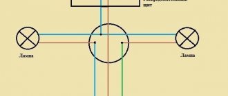
The Euro socket is connected in such a switch block according to the diagram given in the article “How to connect a chandelier.” According to the same scheme, if necessary, the socket is connected to an ordinary switch.
Schemes for connecting sockets to the electrical network
First connection diagram
To connect with your own hands, you need to know the wiring diagrams for the sockets you will use to do this. Let's start with a connection diagram to a single-phase network, which does not have a ground loop.
Socket connection diagram
Meaning of digital designations:
1 – general safety coupled machine.
2 – automatic switch that disconnects the phase on the line to which the sockets will be connected.
3 – zero bus.
4 – distribution switching boxes. They must be located exactly above the sockets so that the vertical outlet section falls down. Each outlet must have its own connection box.
5 – the cable of hidden or open wiring is conventionally shown.
The main thing is to correctly place the phase on the socket on the left, and the zero on the right. This is an electrician's rule that must be followed.
Second connection diagram
The second scheme - on the one hand, these are also single sockets, but of a different “F” type, with a connection to the ground loop.
Connection diagram for single sockets to a single-phase network with a ground loop
Of the new digital designations in this diagram, only 6 are the connection bus for grounding (PE) wires. Shown in green.
However, another option for wiring is also possible, which is often used, for example, in utility rooms, especially with an open type of wiring. In this case, the ground loop runs from below, along the floor along the perimeter of the walls. And a separate wire rises from it to the socket. And the eyeliner itself on top is the usual phase and zero. The switching on the socket terminals does not change in any way.
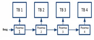
If the connection is to a network without a ground loop, then everything is much simpler. In this case, the sockets are connected with a cable. That is, the phase wire approaches the first, and is connected from it to the second by a jumper. Further, from the second jumper goes to the third. The neutral contacts of sockets are also switched in a similar way.
How much power can an electrical outlet handle?
When connecting high-power electrical appliances to an electrical outlet, the question often arises as to whether the outlet is designed for such power, and how you can check or find out what power this outlet is designed for.
Checking the power of an electrical outlet should be carried out in two stages. At the first stage, by external inspection you can determine the permissible power of the outlet by appearance. Typically, simple Soviet-made sockets with pins with a diameter of 4 mm, type C5, are designed to connect electrical appliances with a power of up to 1.3 kW. If a Euro socket type C6 is installed, then devices with a power of up to 3.5 kW can be connected to it. But the permissible power of the connected device depends not only on the technical characteristics of the outlet.
The socket is connected to the electrical network using wires. Therefore, in the second stage, you need to find out what maximum power these wires can withstand. If the cross-section of the wires is unknown, then you need to open the socket and measure the cross-section of the wire.
| Table of main technical characteristics of electrical outlets | |||
| Socket type | Load current up to, A | Load power up to, kW | Wire cross-section, mm2 |
| C5 | 6 | 1,3 | >1,0 |
| C6 | 16 | 3,5 | >2,7 |
Thus, the power that a particular electrical outlet can withstand depends not only on its technical characteristics, but also on the cross-section of the wires with which the outlet is connected to the electrical network. For example, if a Euro socket C6, which can withstand a load of 3.5 kW, is connected to the electrical network with a wire with a cross-section of 1.0 mm2, then the permissible power that the socket can withstand will be only 1.2 kW. The full load capacity of a Euro socket will be realized with a wire cross-section of 2.7 mm2 or more.
Installation of a socket box
After purchasing materials, you can outline the installation location. The technology used for installation differs depending on the type of wall. Working with concrete, aerated concrete and brick is almost identical, but working with drywall is different. Differences are also observed in the set of tools that are required.
Installing a socket box in concrete, aerated concrete or brick
Working with such wall materials requires specialized tools. You will need to prepare:
- perforator;
- core drill 68 mm;
- chisel or pick for a hammer drill.
Core drill
Prices for socket drills (core drill)
Core drill
First you need to make a mounting hole in the wall to install the socket box using a special core drill. It is installed on a drill or hammer drill. Crowns come in different price segments and differ in cutting edge material. They come in diamond and carbide. Drills also differ in operating mode. Some are used only with a drill, while others are impact, so they are suitable for drilling with chiselling included.
Recommendation! When purchasing a core drill, you need to consider not only its diameter, but also the type of shank. For doors it should be cylindrical, and for a hammer drill sds-plus or another. Otherwise, the incompatible crown will not fit the existing instrument.
If you need to drill reinforced concrete, you will need to use a more expensive diamond-coated bit on the segments, since cheap equipment breaks. You also need to set the optimal number of revolutions recommended in the instructions for the drill.
There is a concrete drill in the center of the cylindrical crown. It is used for alignment. The protruding drill is placed in the center of the future socket box and deepened into the wall until the ring begins to be drilled with a crown. After this, you need to stop drilling and remove the alignment. This will prevent the protruding part of the tool from making a through hole. The centering drill is removed by knocking it out with a wedge or unscrewing a special clamping bolt.
Drilling into the wall
If you need to install a block of sockets, then you need to look at their instructions, as well as the parameters of the socket boxes and determine the center distance. Usually it is 71 mm . To make everything smooth, ideally, immediately after removing the crown to remove the centering drill, you need to make markings from the small hole along a horizontal line in increments of 71 mm . The resulting points will be used in the future to center subsequent drillings.
Marking for a block
After drilling, a circular hole will remain. All that remains is to knock out its central part. This can be done conveniently using a hammer drill with a lance. You can get by with an ordinary hand chisel and hammer. You need to insert the tool into a narrow strip of a larger drilled circle and strike. As a result, the central part will fall out. When working with aerated concrete or brick, this is not difficult. It will be more difficult to knock out concrete if it is reinforced with steel reinforcement.
Installation sequence
Having a hole ready, you can cut a groove in the wall to the ceiling, where the junction box is located, in order to make a branch of the power cable. To compensate for the error, the laid cable is taken 30-40 cm . In the future, the excess can be cut off. When moving on to laying the cable and connecting to the junction box, you will need to turn off the power to the room.
Junction box
After preparing the groove and the hole itself for the socket box, you need to insert the installation box into it and check the depth so that nothing sticks out. Next, you should prepare a thick mortar. It is most convenient to use alabaster and gypsum plaster.
To insert the power wire into the box, you need to break out the window using pliers or cut it off with a knife. In such places, manufacturers make the plastic thinner to allow mechanical extrusion. Next, you need to place a little solution deep into the hole, and then insert the box with the wire inserted into it.
Gluing socket boxes
The socket box should be leveled using a level. If it has only two vertical or horizontal fasteners, then their orientation must be selected depending on the characteristics of the purchased outlet. If there are 4 fasteners, this does not matter.
Socket box with two fastenings
The side cavity between the box and the wall is also filled with solution. If alabaster was used, then after 3-4 hours the installation box will sit securely. You should wait until the solution is completely dry and stops evaporating. Under no circumstances should foam be used to secure the socket boxes, as it is a flammable material.
Advice! If you need to install one or more sockets, then it is not advisable to buy an expensive crown. Holes can be cut with a grinder. In this case, the amount of dust from the work increases. Although accuracy suffers, everything will then be covered with plaster. To cut with a grinder you will need a diamond wheel.
Work as an angle grinder
Prices for popular models of wall chasers
Wall chaser
Video - Installation of socket boxes in a concrete/brick/aerated concrete wall
Arrangement of electrical sockets
As explained above, there are two types of sockets, C5 and C6. Let's take a closer look at what their differences are.
Electrical socket arrangement C5
Despite the huge variety, all sockets are designed in the same way according to the principle of operation and differ only in the shape of the contacts and the material of the body and cover. The design of the C5 socket is very simple. On a ceramic or plastic base, two contacts made of thin brass (thin in order to maintain spring properties) are fixed with adapter iron plates about two millimeters thick by means of screws threaded through the base. Steel plates also serve for threaded connection of wires.
From above, the entire structure is closed with a lid, which serves to protect people from electric shock and prevent the ingress of foreign objects. The cover is screwed to the base using a screw, which is usually located in the center of the socket. The cover has guide holes for easy insertion of the plug when connecting electrical appliances. Depending on the location of the socket installation (in the wall or on the wall), the base is supplemented with the necessary elements for fastening.
The socket shown in the photo above has one significant drawback. Over time, the springing properties of brass, according to Hooke's law, weaken, the pressure deteriorates, and the resistance between the contacts of the socket and the pins of the plug increases. This leads to heating and even worse contact. Eventually the socket fails. Signs of poor contact can be easily detected by touching the pins of the plug with your hand immediately after finishing operation of a powerful electrical appliance, for example, an electric kettle, iron, or hair dryer. Be careful, the pins may be hot enough to cause burns.
The design of the socket below is freed from this drawback. A steel spring is additionally installed in the body, pressing the rectangular brass plate against the thin-walled one. As a result, the spring properties of the contact do not change over time. It is universal and you can insert plugs with pin diameters of both 4 mm (rated for current up to 6 A) and 4.8 mm (rated for current up to 16 A).
And yet, even this electrical socket for impeccable long-term service requires the addition of a spring washer, which is called a Grover and ensures constant contact of the contacting parts over time.
Electrical socket arrangement C6
The C6 type socket is practically no different in design from the C5 socket, with the exception of one, the presence of an additional flat contact for connecting the yellow-green
ground wire colors.
When the plug is inserted into the socket, the pins fall into the sockets of a thin brass plate, and the brass U-shaped plate of the socket is pressed against its side grounding contact on both sides. Thus, grounding is carried out.
The photo also shows how you need to connect the wires to the socket for the case of parallel connection of sockets. If the C5 socket is replaced with a C6 socket in an apartment with electrical wiring in which there is no grounding wire, then the grounding contact of the C6 socket is left unconnected.
Pilot type extension device
A plug with a cord, at the end of which there is a block with sockets and a switch, is often called a Pilot. The pilot is designed in the same way as a regular socket, only the sockets are made of two brass strips in length, depending on the number of sockets. An earth wire strip is placed in the center. In addition, a fuse or automatic fuse is often installed in the Pilot.
Sometimes a simple chain of capacitors and inductors is placed on a printed circuit board to filter impulse noise coming from or coming from electrical appliances. This filter only works if the pilot is connected to ground. If there are only two wires in the wiring and there is no ground, then the filter in the pilot will not work.
Pilots sometimes stop working. The switch is unreliable; I have encountered cases where a key fell out due to wear of its latch; sometimes the key breaks into pieces. I also had to deal with contacts that burned out. In such cases, the switch must be replaced with a new one. To remove the switch from the Pilot body, you must first unsolder the wires from its terminals and then press the latches from the inside. You can temporarily short-circuit the switch terminals (the places where the jumpers are installed are marked in red in the photo) or solder the cord from the plug directly to the brass strips with sockets for the plug pins.
Sometimes a fuse trips or blows. If the fuse in the Pilot is automatic, then you just need to press a button, usually a small black one, and operation will be restored. If a fuse blows, it needs to be replaced or repaired.
Installing sockets in drywall: technology tricks
Builders use two different methods of using plasterboard sheets when renovating an apartment for:
- final leveling of surfaces and creation of perfectly flat planes;
- production of partitions and walls.
In the first case, the sheet is glued closely to the base plane, and concrete, brick or other material is located immediately behind it.
In the second option, an empty cavity is created behind the sheet, allowing hidden lines and electrical installation products to be placed in it.
These two factors determine how the installation of sockets in drywall should be done.
If the sheet is tightly positioned on the wall, a hole is cut in the latter for the socket box and deepened with a hammer drill. Further work is carried out using the technology described above for concrete.
Below I tell you how to simply and quickly mount a socket into a sheet of drywall, when there are no foreign objects behind it that would interfere with its installation.
The design of the socket box has two pairs of screws:
- One pair secures the socket mechanism in the installed plastic housing.
- The second one fixes the socket box with movable claws on a sheet of drywall.
Installation technology: method No. 1
We use a crown to cut round holes with a diameter of 68 mm. They are widely available for sale and are included in the kits of most craftsmen.
Use a drill or screwdriver to drill a hole. Since the base of the sheet is a very soft material: a paper base and compressed chalk, better drilling occurs when the teeth of the crown are rotated counterclockwise - reverse reverse.
Insert the socket box into the prepared hole by hand and tighten the screws for tightening the legs tightly.
The work is done. With this installation method, the upper plane of the socket box protrudes above the plane of the drywall by the thickness of the rim of the plastic cover of about 1 mm.
A certain part of the rosette mechanisms will hide this protrusion with its decorative cover. But not all. If thin wallpaper is pasted on top or the wall is painted, the resulting gap will become noticeable.
A small penetration into the drywall will help get rid of it.
Method number 2: flush mounting
Here, the edge of the adjacent cardboard is additionally cut to a depth of the top layer of cardboard of about one millimeter.
The easiest option is to use a regular construction knife. However, they need to work carefully. The blade should be guided so that it does not go deeper than 1 mm and does not remove an edge that is too wide.
Large damage to the top cardboard layer weakens the strength of the edges of the hole and over time, a roughly installed socket along with the socket box may fall inside the wall.
Therefore, chamfering is recommended to be done with a professional tool. However, it is quite expensive. But there is a way out: using a crown to cut holes in the tiles to 73 mm.
It is used for initial processing of the surface layer, forming a chamfer.
The recess should only penetrate the paper to a total depth of no more than 1 mm. And then in the center of this hole they work with a regular 68 mm crown.
Now I propose to compare the quality of these three methods of installing socket boxes.
On the left, number 1, is a housing mounting option with a protrusion. No. 2 and 3 - recessed edges. The method of cutting with a knife is shown in the second picture, and processing with a 73 mm crown is shown in the third.
As you can see, the latter method is distinguished by accuracy and professional precision.
All three hidden methods of installing sockets in drywall are used by craftsmen in their practice. Your task is to choose the most suitable one: decide on your design preferences or fastening reliability.
We have decided on the options for installing one outlet. When it is necessary to place a socket block on a similar wall, then proceed in the same way.
You just have to first draw its center line strictly along the horizon line and mark the centers of the holes on it at a distance of 72mm from each other.
Rules for connecting electrical outlets
In modern sockets and switches, the wires are connected by clamping a straight section of wire exposed from insulation between the screw and the contact pad. This type of connection is not optimal, since the area of contact of the wire with the contact pad of the socket will be determined by the area of the thin line of contact of the wire.
To increase the contact area several times, if the design of the socket allows, you need to twist the end of the wire into a ring and flatten it with a hammer on an anvil.
This is especially true when forming a ring of stranded wire soldered with solder. Instead of a hammer, you can add flatness with a file, grinding off the ring a little at the points of contact with the contacts.
Linear expansion due to temperature changes is not the same for different metals. Aluminum changes its linear dimensions especially strongly, then, in descending order, brass, copper, and iron.
Therefore, without the use of growers, which are shown in the photo, the contact deteriorates over time and it is necessary to periodically tighten the screws to restore it. The Grover does this work for you automatically.
an ideal threaded connection of wires to socket contacts should be made
.
How to connect an outlet
For convenience, the wires for the socket should protrude 50 - 80 mm.
To ensure that the future socket stands level,
periodically use a level.
1.
First, mark with a pencil the place where the socket will stand, after placing it in a box or a special recess (if you decide to install the socket without a box).
2.
Carefully pull out the wires, the ends of which are stripped of
10 mm of insulation.
Please note that the wires should not be intertwined.
3.
We are considering connecting a modern socket with three wires, one of which is the ground wire, the second is the phase, and the third is the neutral wire.
The socket with an internal block has three terminals.
It is to these three terminals that you need to connect the three wires of the socket.
4.
The internal socket block has mounting screws on the front side. If you screw in these screws one by one with a screwdriver, the external tabs on the socket will begin to move apart and rest against the plastic box or directly against the wall (depending on what exactly you have).
Thus, we attach the internal block according to the previously made markings.
Attention!
The mounting screws on the front side of the internal block of the socket should be screwed in one at a time, then the entire structure will be secured evenly.
Modern sockets are increasingly less often made on the basis of the above-described fixing tabs. Recently, preference has been given to sockets, the housing of which is fixed to an internal plastic box.
5.
All that now needs to be done is to snap the protective frame or socket body into place, and tighten the screws, if any.
Parallel connection of two or more outlets
Sometimes it is necessary to install another one not far from the mounted outlet, for example, on the other side of the wall in an adjacent room.
In this case, the ends of the new wire are connected parallel to the already suitable wires to the outlet. The phase wire must be connected to the right socket of the socket. You can connect aluminum wires to sockets without restrictions, since the terminals are usually plated with chrome. But if you connect another socket in parallel, then it is necessary to exclude direct contact between the copper and aluminum conductors, or coat the copper wire with solder (tin it). If you are wondering why connecting aluminum wires to copper is not recommended, then read the article “Connection of aluminum wires”.
Typical types of sockets
The reasons why you need to change the outlet can be very different - from a full-scale repair to a simple breakdown. Faced with such a problem, you have to choose the right product in a store or market.
Manufacturers offer a wide variety of models in shape, color, and purpose. It is difficult for an inexperienced person to immediately decide what exactly he needs.
The sockets offered by designers sometimes amaze the imagination with their breathtaking shapes. And modern materials used to decorate them are very diverse - wood, glass, stone
Sockets offered by many manufacturers differ not only in appearance, but also in the type of installation. Depending on how the wire is laid, you will need an appropriate outlet.
Based on their location relative to the wall on which the electrical outlet is installed, there are 2 types of sockets:
- built-in;
- invoices.
Built-in ones are used for installation in plasterboard walls, brick or concrete walls. The main distinguishing feature of such sockets is that their electrical parts, like the entire wire, are immersed in the wall. To do this, a special groove is cut into the wall using a hammer drill. It houses wires enclosed in a corrugated pipe.
A special recess with a diameter corresponding to the diameter of the mounting box is cut under the socket. This hole may be slightly larger, but in no case should it be made smaller. The socket box should not be subject to deformation during installation.
The socket for internal wiring is used much more often than overhead models. It is safer to use
Built-in models are in demand among residents of megacities and other populated areas. They are popular in houses and apartments with small children. These sockets fit perfectly into the interior, thanks to the rich color palette offered by the manufacturers.
Surface-mounted sockets differ from built-in sockets in their appearance - they are completely located outside. Their electrical mechanism is hidden only in a decorative box screwed on top of the wall. The wires also go over the wall, covered with a special cover.
A surface-mounted socket is most often used in the office. It is important that all wires are well insulated, and that there are no taps or other sources of water nearby.
Basically, a surface-mounted socket is used for installation in houses with wooden walls.
Depending on the internal structure of the working mechanism, sockets are:
- with a screw clamp, when the wire inserted into the socket mechanism is fixed between plates connected by a screw. If the wire becomes flattened during use, simply tighten the screws;
- with spring terminals. Here the contact hole for the wire is expanded by pressing a special key. Over time, when the fastening weakens due to deformation of the wire, it is necessary to remove the flattened part with pliers and reconnect it.
Depending on what wiring the socket will be used for, there are two and three contact ones. Two-pin sockets are sockets without grounding. Their main advantage is lower cost.
In new buildings, wiring is laid that corresponds to modern living conditions - using three contact wires
Three-pin - with grounding. They are installed in rooms where electrical appliances that require grounding will be used - computers, washing machines and others.
It is dangerous to install two-pin sockets in rooms with high levels of humidity, near showers and sinks
Before purchasing an outlet, you need to pay attention to its back wall. It indicates what load and number of phases it is designed for. Most often, the current value corresponds to 16A and the voltage is 220 volts. However, to connect an electric stove, most often it is necessary to connect a separate line and install a three-phase socket.
If you need to connect a device with a large load, it is better to connect a three-phase network. Here you need to install a special socket that can withstand a voltage of 380 volts and a load of up to 32A
The time has passed when there was no special choice of sockets and you bought what was on store shelves. Now manufacturers, competing with each other, are developing various types of sockets in order to attract more customers.
For home use, you can choose the option that is most suitable for a particular room, for example, for installing an electrical point in the bathroom, in a swimming pool or in a combined bathroom, and for installation within the entrance area of a private house.
For bathrooms it is convenient to use special models - with a protective cover. In addition, this type of sockets is made with a high level of protection from dust and moisture.
Young parents like to install sockets in which the holes are covered with special covers - protective curtains. This allows them to additionally protect their growing children who show interest in studying surrounding objects.
The socket openings, covered with curtains, open depending on the model. Sometimes just inserting the plug is enough, in other cases it requires some effort
Also very attractive are socket models equipped with a current indicator, a timer that can be programmed as needed, or options with a plug ejector.
Designers came up with an interesting solution for children's rooms - an illuminated socket. A child who wakes up in the middle of the night will not be afraid of complete darkness
In the family of products for installing electrical outlets, there is a special group - retractable sockets, the features of the device and installation of which we recommend that you familiarize yourself with.
How to move an outlet to another location on the wall
When installing furniture or for other reasons, sometimes it becomes necessary to move the socket to another location, move it to the side or lower it down. In this case, you have to either replace the entire wire from the junction box to the new installation location or extend the existing wires. It is not advisable to change the wire in a renovated apartment; installing an additional junction box is also not always acceptable. It is best to build up the wires using the technology described in the website article “Connecting broken wires in the wall.”
An example of moving a socket to another location on the wall
When renovating an apartment, I took advantage of the situation and moved one of the sockets from one place on the wall to a more convenient one. Until this time, all hands had not reached.
At a new location on the wall, where it was necessary to move the socket, a metal box was installed and a groove was made for laying an additional wire; since the length of the electrical wiring wire was not enough, it became necessary to extend it.
For the extension, we took an available stranded copper wire with a cross-section of 1 mm2, which is quite enough to connect electrical appliances with a power of up to 1200 watts to an outlet.
At the end of the conductors that will be connected to the socket terminals, rings were formed and tinned with solder. The wire itself, consisting of two separate conductors, for ease of installation and reliability, was threaded into a vinyl chloride tube and laid in a groove made at the seam between the bricks.
To ensure that the wire did not fall out of the groove before covering with plaster, it was secured with two self-tapping screws.
After installing the socket and covering the wire with rotband, it is time to perform the splicing. Since the wires are copper, the most reliable method was chosen, connecting the wires - twisting followed by soldering. The current-carrying wire came from the next room through the wall; at the point where it came out, when drilling the wall, a brick chipped and a small void formed. I decided to hide the connection point of the wires in it. If there was no ready-made recess, you could hollow out a recess in the brick yourself in any convenient place.
Next, the wires are shortened to the required length, the insulation is removed and the conductors are tinned with solder using a soldering iron. Please note that the wires are shortened to different lengths to completely eliminate contact with exposed parts of the wires.
The next step is twisting the wires. Before twisting, wires that are longer must be fitted with insulating tubes. The color in the photo is red. Since the stranded wire is softer, I wound its ends onto single-core electrical wiring wires.
Since the wires are already tinned, to connect them reliably, it is enough to simply heat the junction of the wires with a soldering iron and fill it with tin-lead solder.
Then an insulating tube is stretched over the junction of the wires. If you don’t have a tube at hand, you can simply cover the exposed wires with three layers of insulating tape.
After insulating the connection point, the wires must be tucked into the wall cavity and covered with plaster. But it is better, before applying plaster, to close the cavity with a plate of any material. Thick cardboard, a piece of tin from a tin can and any other material will do. I made a cover from fiberglass in the shape of a hole in the wall.
Next, a small amount of solution is diluted; cement, alabaster, gypsum and any other plaster are suitable. I covered the joint with rotband. Using a spatula, the joint is leveled with the level of the wall surface.
Of course, it was possible to cover the junction of the wires with plaster while leveling the walls, but it is better to complete the work started completely, so that later, when leveling the wall, you do not waste extra time. The rotband solution lasts only 20 minutes and when working with it, every second counts.
The socket was moved to a new location and now nothing prevents us from continuing to repair this section of the wall.
Installing sockets in a concrete wall: how to do it easily and quickly
Modern panel buildings made of reinforced concrete slabs are equipped with wiring hidden in building structures not only for decorative purposes, but also to restrict access and solve security issues.
Installation of sockets in a concrete wall is done using a special technology using preliminary installation of socket boxes. They act as a housing and protect the plug mechanism from foreign objects.
Sockets for closed installation are available only with a front cover. Their mechanism is open on the sides and back.
Cables in a concrete building are laid in cavities specially made at the factory.
Typically, during housing construction, cable channels are placed horizontally and vertically at right angles. In panel houses this rule is often violated. In order to save material, wiring is carried out along the shortest paths.
You need to know them. This information is available in housing and communal services organizations, and local electricians have already studied it well.
However, not everyone is satisfied with such wiring and residents often need to move an outlet or switch or completely lay a new one by cutting grooves in the concrete and placing cables in them.
This process is complex and physically difficult. A professional tool helps make it easier and faster: a wall chaser.
It quickly processes panel walls, making two parallel grooves at once with its cutting discs. Dust from concrete processing is immediately sucked through a flexible hose into a construction vacuum cleaner with a protected electric motor.
It is convenient to make cavities in the wall for socket boxes using a hammer drill with a special head - a crown made for making round cavities in concrete. Its tips are made of refractory plates that are resistant to high abrasion and impact loads.
Such crowns allow you to conveniently make cavities not only in a concrete wall, but also in brick, foam blocks, and stone.
A socket box is installed in the cut-out recesses and a cable is inserted into it to connect to the sockets. The picture below shows the technology for performing this work in 4 stages:
- fitting;
- coating with putty mixture;
- installation in a cavity;
- leveling plaster.
When the plaster mixture has dried in the socket box, you can install the socket mechanism. But before starting this operation, it is necessary to check the condition of the installed cable and its technical serviceability.
When connecting a block of sockets with a cable, in series one to the other, cable jumpers are placed between them. Their length should protrude 15-20 centimeters from each socket. In short, it's not worth doing.
The fact is that copper wire with a cross-section of 2.5 mm square has quite high rigidity. It is not convenient to connect the short ends, and it will be very difficult to properly insert the mounted socket mechanism into a limited space.
Therefore, the rigidity of a thick wire is compensated by its length and preliminary bending with a snake. It begins to work like the bellows of an accordion, which allows you to conveniently insert and remove the socket mechanism.
Saving on short ends, and especially pulling the wire from the back side of the cavity, as is practiced by some “aesthete electricians,” makes it difficult to carry out preventive work and subsequent repairs. It's not worth doing this.
The short ends of the wire pose a particular danger to aluminum cores. Although they are softer, they are less durable. After several bends in one place, the aluminum wire quickly breaks off.
When the end is short and has fallen off, you won’t be able to pull it out. In such a situation, you have to experiment with installing extension cords or completely replace the wiring.
But here the apartment owner should think in advance. Many people simply plaster the cable in the wall groove without placing it in the corrugation.
To remove it you will need to hollow out everything again. Therefore, only well-tested and reliable cable products can be installed this way, and the ends of the wires can be made long.
Connecting wires to socket contacts
There is a constant debate among electricians about which side of the plug socket the phase and zero potential starts from. I think this is not important. You can always pick up a voltage indicator and use it to figure it out.
However, I always recommend doing everything in the same apartment or private house the same way. This principle facilitates installation and troubleshooting and emphasizes the employee’s culture.
How to wire a protective PE conductor
If the phase and neutral wires are often made composite and assembled in separate sections through junction boxes, then this is prohibited with the protective PE conductor.
It must be laid in one piece directly from the detachable electrical point to the busbar of the indoor distribution panel without any breaks or additional connections.
This is dictated by safety requirements. And they must be strictly observed.
Types of sockets by type of connectors
There are at least 12 types of socket plugs that are used in different countries. This classification was proposed by the US government and has been adopted by most other countries.
Type A. Initially, the standard for this outlet was adopted in the USA, and then it was picked up by 38 other countries. It has two flat rectangular contacts arranged in parallel. There is no grounding conductor here. Such sockets can still be seen in old buildings, as they are compatible with the plugs of modern electrical equipment. However, they practically never appear on sale.
Type B. This is an improved Type A with the addition of a ground pin. If you bought a household appliance from the USA, then it will probably have a plug that fits such an outlet. In addition to the USA, this type is also used by Mexico, Venezuela, Canada, Colombia and other countries.
Type C. This is the type most familiar to us since the times of the USSR. It consists of two round contacts located in parallel, without grounding. This type of socket is used in most countries in Europe and the Middle East. Although with the advent of type F models it gradually begins to die out.
Type D. An obsolete type of sockets, introduced at one time by the British in countries that were former colonies of England. Such sockets can very rarely be found in old English houses, as well as in India.
Type E. Modern standard adopted in France. It differs from type C by the presence of a ground located above the contacts. Such sockets are widespread in France, Belgium, Poland, the Czech Republic and Slovakia. Sometimes they can be found on the territory of modern Russia.
Type F. This is the most common European standard of sockets in our country with two conductive contacts and two grounding contacts located at the bottom and top. Such sockets first appeared in Germany and became known as “Shuko” (“protective contact”). The size of the current-carrying contacts in the device here is slightly larger than in Type C models, so some old Soviet thin plugs may not fit tightly into the socket.
Type G. This standard was introduced by the British and involves the use of plugs with a fuse inside them. You can also use Euro plugs through an adapter, but the adapter must have a fuse (ground contact). This type of outlet is most widespread in Ireland.
Type N. An exclusively Israeli version of sockets, in which three contacts form the letter “Y”. Until 1989, products with flat contacts (as in the figure) were used, but now they are mainly with round ones. Unfortunately, there are no adapters for plugs for such sockets (although in China they are probably already in development) for other types of sockets, so buying Israeli household appliances and using them in our country is a problematic task.
Type I. This is an Australian standard and is also used in New Zealand, Fiji and Papua New Guinea. Two current-carrying contacts are located at an angle, and at the bottom there is a ground contact. If you suddenly go on a trip around the world and find yourself in these countries, be sure to get an adapter.
Type J. Standard adopted by Switzerland. It is somewhat similar to type C, only the grounding contact is located between the current conductors and is slightly lowered down. Euro plugs can be used with it without any adapters.
Type K. Danish type of sockets. The difference from the French standard is only in the location of the grounding contact, which is installed directly in the plug of the device.
Type L. A standard that is common in Italy. It is compatible with type C Euro plugs, so modern electrical appliances can be safely connected to Italian sockets. The middle contact is grounding.
Types of sockets by installation method
Built-in . The most common design of sockets involves installation in a special socket box hidden in the wall. Only the socket body and contact output remain outside. Models with grounding additionally have grounding antennae.
Invoices . This type of sockets is used when it is necessary to lay external wiring. Here, all the filling is completely contained in a protected housing. The wire is inserted inside through a special hole. It is much easier to damage such an outlet simply by passing by. However, for fixing somewhere in the garage or on wooden walls it is a very good thing.
Both overhead and built-in sockets are available in single, double, triple or quadruple types. There are a huge variety of each type on sale, so you can easily choose the appropriate option for your apartment.
- Exploitation
Is it necessary to install grounded sockets in the apartment?