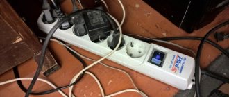
Tuesday, February 04, 2014 11:33 + to quote book So the PS/2 mouse failed. Defects can be different, for example, the mouse began to produce two clicks with one key press. Why did I use this defect as an example? Because in this case it is difficult to blame the button on a malfunction. And you can’t take such a mouse to the workshop, since repairing the mouse will cost at least twice as much as buying a new one. So, is it okay to throw away the mouse? It’s not at all necessary if you have some repair skills (for example, the ability to carefully solder) or if you have a friend who has these skills and doesn’t mind ten minutes for you.
Wiring out the PS/2 mouse connector
| No. | Signal |
| 1 | Data |
| 2 | not involved |
| 3 | Ground |
| 4 | +5V |
| 5 | Clock |
| 6 | not involved |
PS/2 computer mouse repair
The main reason for all the mouse defects that occur is the deterioration of the conductivity of the wire. The defect is very easily calculated using an ohmmeter. On a serviceable wire core, the ohmmeter will show 1-10 Ohms, and if the wire core is faulty, 150 Ohms and higher.
Now how to repair it. The PS/2 connector itself is not collapsible, but as it turned out, we don’t need it. As it turned out, the fault lies in the section of the wire from the internal connector of the mouse to the wire exiting the mouse. (For some reason, all manufacturers have recently decided that in this place there should be a transition from internal to external wiring + it is at the point where the wire exits the mouse that the greatest load on the wire occurs). In general, we bite out this section of the wire (you can go in two ways, just bite off the edge of the wire from the side of the mouse and solder it back into the mouse, or bite out the section and solder the wire (I prefer the second option (the joint will still be inside the mouse))) we strip and tin the wires cable, and restore the integrity of the wire. (By the way, immediately after biting, we check the integrity of the wire cores)
Computer technology does not stand still; it is constantly being improved, and desktop computers are often replaced by laptops. But a laptop also needs a mouse, and where to put the old mouse with a round connector? And even more so, if it works great and ergonomically fits your hand very well... Throw it away?
No, why, there is a way out - it needs to be converted to a USB connector.
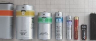
There are 2 options: you can simply make an adapter, or remove the old cable on the mouse and connect a new one - with a USB plug. As you can see, the wiring diagram is quite simple - only 4 wires. It is enough to take some old cable with a USB plug, from a camera or mobile phone, for example, or you can buy such a cable at a flea market and replace it on the mouse.
And the purpose of the USB connector wires, based on color and numbers, is as follows:
1. red - power, 5 Volts, 2. white (gray) (D-) - transmits data from the computer to the mouse, 3. green - transmits data from the mouse to the computer (D+), 4. black - ground (case).
Based on the colors of the wires, you can quickly re-solder the cable, but I still advise you, before unsoldering the old cable, ring it with a tester and once again make sure that the colors of the wires correspond to the numbers on the connector. As practice shows, the human factor is still present and mistakes also happen.
Using this wiring diagram, you can convert a keyboard with a round PS/2 connector to a USB connector. Everything is the same, connecting the right wires to the right contacts... I think this article will help you usefully recycle (adapt) outdated, but still quite good and functional parts from old PCs.
Over time, the question arises of how to enter data into the microcontroller
?
The classic solution that most of us come up with is to use buttons
tracks
and
contact pads
for
buttons
on the board , then
solder
, decide how
to monitor
button presses - by
interrupt
or by
polling the state of the buttons in a cycle
.
If there are a lot of
, they
will take up
a significant number
pins
. The path is thorny.
I suggest using what we have at hand - a simple PS/2 computer keyboard
. Pros:
- the thing is not expensive;
- sold at any
computer store - 101 keys available
- The keyboard will take up only 2-pin
microcontroller for the clock signal and data.
ATmega328P as a microcontroller
or
Arduino UNO
.
Pinout of USB 2.0 connectors
USB (Universal Serial Bus) The whole variety of USB version 2.0 connectors is shown in the picture below. The picture is clickable.
To avoid discrepancies: In all tables, the type of connector is given from its external, working side (and not from the mounting side!), unless otherwise specifically stated. The insulating parts of the connector are marked in light gray, the metal parts are marked in dark gray, and the connector cavities are marked in white.
Well, and a simplified, so to speak, practical diagram:
The name of a particular connector is provided with letter indices.
Connector type:
- A - active, power supply device (computer, host)
- B - passive, connected device (printer, scanner)
"Gender" of the connector:
- M (male) - plug, “male”
- F (female) - nest, “mother”
Connector size:
For example: USB micro-BM—plug (M) for connecting to a passive device (B); micro size
USB connector pinout (jacks and plugs)
The purpose of the wires in the USB cable is as follows:
- Red VBUS (+5V, Vcc - Voltage Collector Collector) +5 Volts DC voltage relative to GND. Maximum current - 500 mA
- White D-(-Data)
- Green D+ (+Data)
- Black GND - common wire, ground, minus, 0 Volt
Mini and micro connectors contain 5 contacts:
- Red VBUS
- White D-
- Green D+
- ID - not used in connectors “B”; in connectors “A” is closed to GND to support the “OTG” function
- Black GND
Among other things, the cable contains (though not always) a bare Shield wire - housing, screen, braid. This wire is not assigned a number.
Good news
A reversible micro-USB plug is being announced on the Internet, which, like USB 3.1 Type-C, does not require a clear ±180° orientation when connected to a socket.
Mouse and keyboard cord pinout
Some mice and keyboards may have different cable colors than standard. Detailed article about non-standard colors: “Custom USB colors in mouse and keyboard cords”
Read also about connecting mice and keyboards to the PS/2 port
How to unsolder USB?
Well, with regular USB everything is simple - you take a mirror image of the front part of the connector and solder it.
The wiring of the USB mini and USB micro plugs from the mounting side is shown in the picture below. If you are soldering a simple data cable (for connecting a PC and a mobile phone/smartphone/tablet), then do not use the 4th contact. When soldering an OTG cable (for connecting flash drives and other things to a smartphone), connect the 4th pin to the 5th.
Mini and micro connectors contain 5 contacts. Type B connectors do not use the fourth pin. In type “A” connectors, the fourth pin is connected to GND. And the GND contact itself takes an honorable fifth place.
And here is a complete diagram of the USB cable with a screen.
Related materials:
All
USB 3.0 pinout types A and B
Bus version 3.0 has a 10 or 9 wire connection. 9 pins are used if Shield wire is missing. The contacts are arranged in such a way that devices of earlier modifications can be connected.
USB 3.0 wiring:
- A – plug;
- B – socket;
- 1, 2, 3, 4 – contacts that match the pinout of the contacts in specification 2.0, have the same color scheme;
- 5, 6 contacts for data transmission via the SUPER_SPEED protocol are designated SS_TX- and SS_TX+, respectively;
- 7 – grounding GND;
- 8, 9 – contact pads of wires for receiving data via the SUPER_SPEED protocol, contact designation: SS_RX- and SS_RX+.
Pinout of USB ports, pinout of micro USB, mini connector for charging
Currently, all mobile devices and desktop electrical appliances have data ports in their arsenal. Modern gadgets can not only exchange information via USB or micro-USB, but also charge batteries. In order to carry out proper pinout of contacts, you first need to study the diagrams and colors of the wires.
USB cable wire colors
Connector diagram for USB 2.0
In the diagram you can see several connectors that differ from each other according to a certain characteristic. For example, an active (power) device is designated by the letter A, and a passive (connected) device is designated by the letter B. Active devices include computers and hosts, while passive devices include printers, scanners, and other devices. It is also customary to separate connectors by gender: M (male) or “male” is the plug, and F (female) or “female” is the connector socket. There are formats by size: mini, micro and without marking. For example, if you see the designation “USB micro-VM”, this means that the plug is designed to connect to a passive device in micro format.
To pin out sockets and plugs, you will need knowledge about the purpose of the wires in a USB cable:
- The red VBUS (“plus”) carries a constant voltage of 5 Volts relative to GND. The minimum electric current value for it is 500 mA;
- the white wire is connected to the negative (D-);
- the green wire is attached to the “plus” (D+);
- The black color of the wire means that the voltage in it is 0 Volts, it carries a negative charge and is used for grounding.
In mini and micro formats, connectors contain five contacts each: red, black, white and green wires, as well as ID (which in connectors of type A is shorted to GND, and in connectors B is not used at all).
Sometimes you can find a bare Shield wire in the USB cable. This wire has no number.
If you use a table in your work, the connector in it is shown from the outside (working) side. The insulating parts of the connector are light gray, the metal parts are dark gray, and the cavities are marked white.
In order to carry out the correct USB wiring, you need to mirror the image of the front part of the connector.
Connectors for mini and micro USB formats consist of five contacts. Therefore, the fourth contact in type B connectors will not have to be used in operation. This contact in type A connectors is connected to GND, and the fifth is used for GND itself.
As a result of some simple manipulations, you can independently make pinouts for USB ports of different formats.
USB wiring version 3.0 is distinguished by the addition of four colored wires and additional grounding. Due to this, the USB 3.0 cable is noticeably thicker than its younger brother.
Schemes for connecting USB devices to each other and wiring the device plugs:
- PS/2 To USB port
- Joystick Defender Game Racer Turbo USB-AM
- Wiring usb am and micro usb bm, for charging and transferring data to a computer
- USB-OTG
- USB wiring SAMSUNG GALAXY TAB 2
Author: Vitaly Petrovich. Ukraine, Lisichansk.
volt-index.ru
Types of USB connectors, main differences and features
The Universal Serial Bus comes in 3 versions – USB 1.1, USB 2.0 and USB 3.0. The first two specifications are completely compatible with each other; bus 3.0 is partially compatible.
USB 1.1 is the first version of the device used for data transfer. The specification is used only for compatibility, since 2 operating modes for data transfer (Low-speed and Full-speed) have a low speed of information exchange. Low-speed mode with a data transfer rate of 10-1500 Kbps is used for joysticks, mice, and keyboards. Full-speed is used in audio and video devices.
A third operating mode has been added to USB 2.0 - High-speed for connecting information storage devices and video devices of a higher organization. The connector is marked with HI-SPEED on the logo. The information exchange speed in this mode is 480 Mbit/s, which is equal to the copying speed of 48 MB/s.
In practice, due to the design and implementation features of the protocol, the throughput of the second version turned out to be less than declared and amounts to 30-35 MB/s. The 1.1 and 2nd generation Universal Bus specification cables and connectors are identical in configuration.
The third generation universal bus supports a speed of 5 Gbps, equal to a copy speed of 500 MB/s. It is available in blue, which makes it easier to determine whether the plugs and sockets belong to the advanced model. Bus 3.0 current increased from 500 mA to 900 mA. This feature allows you not to use separate power supplies for peripheral devices, but to use the 3.0 bus to power them.
USB connector pinout: regular, mini, micro
In our age of computer technology, smartphones and gadgets, it is difficult to find a person who does not know what USB connectors are. Also, almost everyone understands words such as mini- and micro-USB connector. After all, we use such things almost every day, which is natural. Similar connectors are found on the charger and on all peripheral devices of the computer.
But what to do if the soldering has come off at the base, and there is no way to even understand what color and what contact was soldered to? This is where knowledge should be applied, and now let’s try to figure out which ones.
The wiring of such a plug, or, in other words, the pinout of a USB cable, inherently does not involve anything overly complicated. Once you get the sequence and colors figured out, anyone who can hold a soldering iron can do this kind of work.
But first you need to understand what a USB plug is.
Types of USB plugs
What is a USB connector?
At its core, it is a connector with many capabilities, ranging from USB power to transmitting complex information data. This cable replaced the previously used options for connecting to a computer (PS/2 ports, etc.). Today it is used for all devices connected to a personal computer, be it a mouse, flash drives, printer, camera or modem, joystick or keyboard - USB cables have become truly universal.
There are three types of such connectors:
- 1.1 - its purpose is already outdated peripheral devices with the ability to transmit information at only one and a half megabits per second. Of course, after a little modification by the manufacturer, the transmission speed rose to 12 Mbit/s, but it still couldn’t stand the competition with higher-speed options. Of course, when Apple already had a connector that supported 400 Mbit/s. Now there are also such types, but there are very few of them, since faster USB wires, mini USB, and in general, USB speed occupies a special place in human life. Everyone is in a hurry somewhere, in a hurry to live, there are people who practically do not sleep, and therefore the faster the information is downloaded, the more preferable the connector is, right?
- 2.0. At the end of the last century, the second generation of such connectors was released. This is where the manufacturer has already tried - the transmission speed has increased to almost 500 Mbit/sec. And it was intended mainly for complicated gadgets, like a digital video camera.
- 3.0 - this is really high technology. The maximum data transfer rate of 5 Gbit/s provided this USB connector with demand, which practically reduced the first and second versions to zero. In the third series, the number of wires has been increased to nine versus four. However, the connector itself has not been modified, and therefore you can still use the types of the first and second series with it.
Pinout designations
When looking at the pinout diagram, you need to understand all the symbols that are present on it. Usually indicated:
USB pinout options
- Type of connector - it can be active (A) or passive (B). A connection between a printer, scanner, etc. is called passive. In general, a connector that only works to receive information. Through the active it is possible to receive and transmit data.
- The shape of the connector is “mother”, that is, a socket (F), and “male” is a plug (M).
- Connector sizes: regular, mini and micro.
For example, USB AM, that is, an active USB plug.
The wires should be arranged by color as follows (from left to right):
- The red wire is positive, constant voltage 5V. with a maximum current of 500 milliamps.
- White wire - data-
- Green wire - data+
- Black wire - this wire is common, ground, negative. There is no voltage on it.
But the mini and micro connector include 5 wires with this arrangement:
- The wires are red, white and green - arranged similarly to the first option.
- ID - this wire in connectors “B” is free. In “A” it must be connected to a black wire.
Wiring of contacts in the “mother” of USB 3.0
Sometimes there may be a separate wire without insulation in the connector - this is the so-called “ground”, which is soldered to the case.
According to the presented diagrams, the external side is visible here. In order to solder the plug yourself, you need to take a mirror image of the picture, and as it probably became clear, the microUSB pinout is no more complicated than that of conventional USB connectors.
By the way, if the damaged parts of the cable are intended to be used only for charging mobile phones, it will be more convenient to look at the colors of the wires and solder only black and red. This connector is quite enough for a phone; it will charge it. What to do with the rest of the wires? You don't need to do anything with them.
domelectrik.ru
"SECRETS" OF THE MOUSE
The prototype of a computer mouse - a two-dimensional analogue manipulator connected to a personal computer (PC, or PC) via a serial port that complies with the RS-232 standard, and equipped with a couple of buttons on a convenient and compact body - is considered to be a device created almost 40 years ago in Stanford Research Institute and incorporates a number of principles authored by the famous inventor Douglas Engelbart.
In appearance, it is a wooden box with a “tail” - a communication cable. Obeying the movements of the operator’s hand, scouring the table on wheels, counting their revolutions and turns, this device seems to sniff out information, which is immediately entered into the computer and controls the movement of the cursor on the screen. Indeed, what a sneaky mouse!.. Modern devices for entering information into a personal computer (PC) - optomechanical, optical and other computer mice - also look like the nimble and successful Mickey Mouse. Obedient to the will of the owners (users), they transmit to the system information about their movement along the plane and pressing the buttons located on top, in the front part of the case.
Perhaps the most popular type of computer mouse is the optomechanical one (Fig. 1a), inside of which there is certainly a freely rotating and rather heavy rubber-coated ball. Through a hole in the center of the bottom (and in many designs, located inside a removable ring), it contacts the underlying surface (mat) and, with any movement, transmits rotation to two mutually perpendicular rollers with coordinate disks. Sensors - two open optocouplers (LED - photodiode). In the working lumen of each of them, a coordinate disk with slots rotates during operation. Optocouplers can be either solid structures or individual elements installed on a printed circuit board.
Focused LED beams, passing through the slots of the coordinate disk, periodically overlap when the mouse moves, and corresponding electronic current pulses appear at the output of photodetectors (photodiodes). The rest is done by electronics...
Bus Mouse (bus mouse) is quite rightly considered a long and hopelessly outdated version of a computer manipulator. There are no optocouplers inside such a peripheral device. Rotating coordinate disks here interrupt not the course of LED beams, but brush contacts of the simplest electromechanical sensors; Signal processing is performed by a special adapter (usually an ISA board). The cable is rare, 9-wire, the connector is also specific. The main drawback is the adapter itself: it takes up a slot on the board, I/O addresses, and an interrupt request line...
Serial Mouse, on the contrary, refers to a fairly common type of computer mouse with a serial interface. This peripheral device is connected to one of the 9- or 25-pin COM port connectors.
Inside any Serial Mouse there is a built-in microcontroller that processes signals from coordinate sensors and buttons. Each event (movement or pressing and releasing buttons) is encoded by a binary message via the RS-232 interface. Asynchronous transmission is used to transmit information, and bipolar power comes from the interface control lines. Disadvantage of Serial Mouse: this device occupies a COM port and requires exclusive use of its standard interrupt line (IRQ4 for COM1 and IRQ3 for COM2).
Most often you have to deal with MS-Mouse and PC-Mouse. Although they are varieties of computer mice with a so-called serial interface, they nevertheless use different signal sending formats; If the installed driver does not match the true one, erratic, jerky movement of the cursor across the screen is inevitable.
A subtype of serial mouse, the PS/2-Mouse is nothing more than the result of past experiments by IBM with PS/2 series computers, which were produced for a very short time. The interface and cable connector of this peripheral device are similar to those of a keyboard.
It just so happened, but the adapter and PS/2 connector are “certainly present” on all modern motherboards. Well, the controller of this mouse can either be part of the keyboard controller or occupy additional I/O addresses. It's also worth knowing that PS/2-Mouse uses IRQ 12.
Serial Mouse pinout for 9- or 25-pin COM port connectors
There are a number of annoying misunderstandings associated with the PS/2-Mouse and Serial-Mouse 1 serial interfaces that sometimes arise among beginners who forget that...
Firstly, the PS/2 interface uses a unipolar signal with TTL (transistor-transistor logic) levels and strictly requires the so-called unipolar power supply: +5 V relative to the GND bus. But the RS-232 interface used in COM mice is characterized by an exclusively bipolar signal (with trigger levels +3...+ 10 V and -3...-10 V) and only a bipolar (relative to the GND bus) power supply.
Second, the PS/2 mouse interface uses two separate signal lines: one for data transmission, the other for clock signals. In contrast, a COM mouse uses a single wire, through which the signal is transmitted asynchronously.
Even without going into other details, we can state that these types of interfaces are directly incompatible. True, sometimes you hear a clarification: they say that passive adapters are already being produced, designed, according to “all-knowing” computer equipment sellers, to ensure reliable operation of a computer mouse no matter how it is connected to a PC.
However, be vigilant and careful! The above-mentioned adapters are intended only for universal mice, the controller of which is, indeed, capable of recognizing by the supply voltage which interface it is connected to, and immediately setting the appropriate type of its output signal. Unfortunately, such “advanced” information input devices are still extremely expensive and few in number, so failures when connecting cheap computer mice to a PC via adapters are by no means uncommon. Isn’t it better to immediately purchase “peripherals” with the required interface than to spend money later on any additional devices and accessories with little hope of their effectiveness?!
USB mice (USB Mouse) appeared relatively recently and have already proven themselves quite well, but... To connect them, the computer must have a USB bus.
The optical mouse is also deservedly popular. Having no “mechanics”, she quickly “runs” on a special rug, on the surface of which a network of intersecting black lines is applied. The reflected LED beams are periodically interrupted when the mouse moves, which is recorded by photodetectors (Fig. 1b). The built-in electronics do an excellent job of counting the resulting current pulses...
Among the variety of other computer mice, one cannot help but o. Communication with the PC base units of such manipulators is carried out using not a cable, but a radio signal or infrared rays. There are also mice designed to control the cursor in three-dimensional virtual space.
In a special row are trackball-type manipulators. Although these devices resemble an inverted mouse, the rubberized ball of which must be rotated with your fingers, the rest of the design here is both motionless and more compact, which is highly valued, for example, in laptops. There are trackballs designed to work in computer games and other equipment, aimed mainly at the younger generation. Accordingly, the external design of these manipulators is in a youth or even children's style, but with the obligatory preservation of functional properties while simultaneously increasing reliability.
However, over time, even the most persistent of computer mice and similar devices begin to mope, forced to clock up their not-virtual kilometers day after day. Like any equipment, PC manipulators need cleaning, preventive maintenance and, if a special need arises, repair.
The first thing to do when a previously obedient mouse suddenly begins to move poorly in one direction or another is to check the condition of... the underlying surface. Potholes, oiliness and dirt on it, of course, are unacceptable.
If, say, you are dealing with a dirty rug, and its covering is rag, then it is unlikely that you will be able to fix everything by washing: manufacturers most often use non-waterproof glue. But you can smooth out material that has been wrinkled or rolled during use and lift its pile by rubbing the mat with a brush. However, do not overdo it, because it won’t take long for the fabric layer that begins to lag around the edges to be completely torn off. But polymer mats can be safely wiped in soapy water, removing all the adhering dirt that has sunk into scratches and grooves.
Fig.1. Schematic design of an optomechanical computer mouse (a) and an optical one (b):
1 - underlying surface (rubberized or plastic mat, and in option b - a coordinate plate marked with black lines); 2 — bottom with a working hole in the center; 3 - body; 4 - connecting cable; 5 — elastic sleeve for cable entry; 6 — key with microswitch (2 or 3 sets); 7 — coordinate disks; 8—sources of focused light (LEDs): 9—photodetectors (photodiode); 10 - board with electronic circuit; 11 — pressure rollers; 12 - heavy rubber-coated ball; 13 — lens; 14 - periscope mirror
It is possible that during the operation of the manipulator, dust and small fibers from the mat mixed with the sweat of the palms managed to get through the rubberized ball inside the mouse itself and roll onto the rollers, packing into the places where the axes of the coordinate disks are attached, slowing down the rotation of the latter. Often, mud rags manage to get to optocouplers, clogging the holes through which the LED beams must pass during operation.
You can often see the true condition of the rollers, and even the coordinate disks with optocouplers, without disassembling the mouse or even removing the case from it. It is enough, by turning the manipulator over, to remove only the ball from the socket, held in the bottom by a ring with arrows and the explanatory inscription OPEN (“open”). And then - act, as they say, according to the circumstances.
Dirt adhering to the part can be removed by holding an alcohol swab in tweezers (making sure that the cleaning liquid does not drip into the body, especially if you are using an aqueous solution rather than pure alcohol) or carefully scrape it off, gradually turning the rollers and blowing loose pieces of dirt out of the hole. In a similar way, you should clean the installation sites of the axes, and (with extreme care) the coordinate disks with holes for the passage of LED beams. Well, it is recommended to bathe the ball in a soapy solution, then rinse it in running water under the tap and dry it with a napkin.
Avoid touching already cleaned parts with your hands, otherwise grease from your fingers can easily get onto the rollers, and these are the prerequisites for the very rapid adhesion of new dirt with all the ensuing consequences.
It happens that the rollers are wiped, and the ball is washed with soap, but the expected smooth movement of the cursor on the screen does not occur when moving the mouse across the mat. In this case, look - perhaps a notch was made on the rollers, which was erased due to prolonged use. The necessary roughness can be achieved here with fine sandpaper. Just try not to lose your sense of proportion when carrying out such an important “restoration operation”, which is, of course, easier to carry out if you open the mouse itself, after first unscrewing the screws in the bottom.
There is also a more radical “folk” method of restoring a worn out roller. The idea is to put two rings made of PVC tube or cambric on top of it. This should be done in such a way that the working part of the ball remains hanging in the air, slightly touching the ends of the rings with its sides.
In order for the rings to fit tightly, they do not need to be placed on glue. It’s just that the blank tube should be smaller in diameter than the roller. In addition, it is recommended to dip the rings cut out of it into boiling water for a short time, and then quickly pull them onto the rollers in the places prepared for them. After cooling, the rings will be tightly seated.
Fig.2. Features of the PS/2 Mouse Cable Connector
Pay attention to the pressure roller (conditionally absent in Fig. 1a). Wash this part too, remembering to remove the spring from it in advance.
Although many users, considering a computer mouse almost a consumable item, sometimes prefer not to engage in repairs at all, but rush to purchase a new Mouse (fortunately, the prices for these manipulators, as the advertisement claims, are “quite reasonable”), but... It’s impossible not to take into account that after long work the hand gets used to the mouse, and switching to a new one can be difficult. And sometimes circumstances are such that the store is a bit far away or, say, the type of manipulators you need is already sold out. Perhaps it’s better to pore over the faulty mouse a little and try to “revive” it yourself?
Remove the manipulator board, inspect the installation - there should be no flux residues anywhere after soldering. Know: if the flux is not completely removed, the copper of the conductive elements will begin to gradually deteriorate and through the oxides it will be possible to short-circuit adjacent printed tracks. The board is cleaned by wiping it with a cotton swab moistened with alcohol, preferably clean.
It is hardly advisable to disassemble and repair “rattling” buttons. However, zealous users and owners who are familiar with a soldering iron can try to independently replace “depressed” microswitches by selecting known good ones from their “mouse collection”.
It’s worth remembering that the Serial Mouse’s power supply is bipolar: “plus” comes from DTR and RTS, and “minus” comes from TO. If the mouse with this port does not work, then you need to check the voltage at the output pins of the connector.
It also happens that a specific mouse being connected “refuses” to work with a given port, although it does not have problems with others. The reason may be low voltages under load - according to the standard they must be at least 5 V (absolute value), and if a given port only outputs this minimum, then some Mouse may not have enough of such a “starvation solder” (not enough power to power the LEDs) .
It should also be taken into account that the absence of -12 V is noticed only by devices connected to the COM ports. The power supply should control this voltage (theoretically...), but you may well come across a simplified version of the power supply, which does not pay attention to -12 V.
It happens that after many years of use, the mouse begins to work unstably due to LEDs (they are quite easy to identify - they are connected to a common wire with one pin, and power is supplied to the other through a resistor), which over time lose their former brightness. Look, maybe there’s just too much dust settling on them? Try wiping the LEDs from the side of the built-in lenses, just do not use solvents or metal objects, so as not to cause additional problems.
If no cleaning helps, then try to adjust the resistance of the resistor mentioned above (usually downward). It is recommended to unsolder this element of the circuit, measure its value with an ohmmeter, and in return solder in a new one with a value half as much as the previous one. You can even limit yourself to soldering (in parallel to the standard one) an additional resistor with a resistance of approximately 1 kOhm.
In the case when the previous actions do not bring the expected result and the mouse still does not work, take an awl and rotate the coordinate disk in both directions, touching the awl to those legs of the photo receiver of the non-working optocoupler that go to the main microcircuit. If, when you touch one of the photodiodes, the mouse reacts to the rotation of the roller, it means that the corresponding LED has “aged” so much that it needs to be replaced.
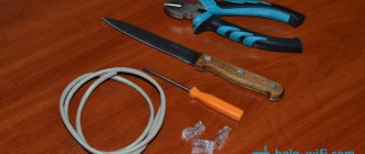
When working too vigorously, some users (especially computer game enthusiasts) manage to break the connecting cable. The outer insulation may look intact, but the mouse refuses to work and is not even recognized by the computer. The worst thing is if the malfunction appears from time to time - in the form of chaotic jumps of the cursor across the screen.
Finding breaks and restoring current-carrying conductors is difficult. Better look - perhaps the cable is “connected” to a standard connector, and you can simply borrow an analogue from another mouse. If you don’t have a “spare” at hand, try cutting a piece of cable directly next to the elastic bushing of the input (this is where they usually break) and solder the stripped and tinned ends of the undamaged wires to the board (in accordance with the table and figure).
You can act differently. “Ring” the connecting cable by bending it in different places and gradually moving from the input sleeve to the connector. As a rule, breaks occur where frequent bends are unavoidable. Moreover, it is usually the wire in orange insulation that is damaged (technological oversights or manufacturer’s negligence?). The insulation at the break point is fragile, and if you pull on the damaged wire, the broken end of the wire will immediately be exposed.
Further. Take a knife (or better yet, a scalpel) and begin to carefully cut the outer sheath of the cable along to the break point and then about 8 mm to have access to the other end of the broken wire. Solder both ends and push the wires back into the sheath, which can later be wrapped with thread or electrical tape (although the latter is often not required at all; the cut on the repaired cable is not even noticeable). If it turns out that the wires of the cable are intact, but the mouse does not work, then it is possible that the quartz (sometimes a capacitor is installed instead) may fail. This means you need to replace it with a known good one.
It also happens that the mouse is simply dropped. As a result, for example, the attachment point of the roller on the bottom of the mouse may break. In this case, replacement is possible - if you have mice from the same company, then simply replace the bottom cover with intact fasteners from another copy.
There are a fairly large number of programs that can make you worry about the “well-being” of the mouse, although it will be completely fine. For example, this is a software joke MouseFX, “slipped” by someone into the “Startup” of the computer. Programs like those developed by Alexey Kulentsov, 2:5020/, version 1.08 from 17-10-96 16:18, distributed free of charge on the Internet, will help you identify this, as well as many other “pranks” of the mouse itself.
A. DOLININ
We recommend reading
- IN THE NAME OF SPANISH NAVIGERS On the dark night from September 18 to 19, 1895, the cruiser Sanchez-Barcastegui went to sea. The day before, during a secret meeting, his commander, Captain 2nd Rank Francisco Ibanez Varela...
- UNLUCKY FLAGSHIP. INSTEAD OF AN AFTERWORD For more than three hours, British ships, including the heavily damaged Camperdown, remained at the site of the death of the Victoria, lifting from the surface of the water not only those who had survived...
USB connector wiring. Wiring diagram:
The USB connector wiring has been developed since 1994, and the development team consisted of engineers from leading companies in the field of IT technologies - Microsoft, Apple, Intel and others. During the research process, one goal was pursued - to find a universal port that could be used for most devices.
Thus, users were provided with a USB connector, which was almost immediately supported by various developers and began to be actively used in a variety of devices, from personal computers to mobile gadgets. However, it so happened that cables with such connectors could not be used everywhere, and they themselves were different, and therefore some require unsoldering a mini-USB connector in order to make the appropriate adapter.
However, few people know how this procedure should be carried out correctly.
Concepts you need to know
Wiring a USB connector begins with learning the basic concepts:
- VCC is the positive potential contact of the power supply. For modern USB cables, the indicator of this contact is +5 Volts, and it is worth noting that in radioelectric circuits this abbreviation fully corresponds to the supply voltage of PNP, as well as NPN transistors.
- GND – negative potential contact of the power supply. In modern equipment, including various models of motherboards, this device is connected by a housing in order to provide effective protection from static electricity or any external sources of electromagnetic interference.
- D- is an information contact that has zero potential, regarding which information is broadcast.
- D+ is an information contact that has a logical unit. This contact is used to broadcast information from the host to the device or vice versa. At the physical level, this process represents the transmission of rectangular pulses with a positive charge, while the pulses have different amplitudes and duty cycles.
- Male is the plug of this connector, which is often called “male” among modern users who wire the USB connector for a mouse and other devices.
- Female – the socket into which the plug is inserted. Users are called "mother".
- RX – information reception.
- TX – information transfer.
USB-OTG
OTG is a method of connecting two peripheral devices via a USB cable without the need for a computer. Also, such a pinout of a micro-USB connector is often called a USB host in professional circles. In other words, a flash drive or some kind of hard drive can thus be directly connected to a tablet or mobile phone in the same way as to a full-fledged personal computer.
In addition, you can connect mice or keyboards to gadgets, if they support the ability to use them. Cameras and other gadgets are often connected to printers in this way.
What limitations does it have?
The limitations that this type of micro-USB connector has are the following:
- Old mobile phones do not have the ability to use them.
- The flash drive must first be formatted for the FAT32 file system.
- The maximum possible capacity of a connected flash drive is limited by the various hardware capabilities of the phone.
- The hard drive will most likely have to be connected to an additional power source.
For example, if we are talking about connecting some kind of USB flash drive to the phone, then in this case the “USB_AF-USB_AM_micro” adapter is most often used. In this case, a flash drive is inserted into the connector, while the plug is connected to the mobile phone.
Cable Feature
The main feature that distinguishes the wiring of a USB connector in the OTG format is that in the plug, pin 4 must be connected to pin 5. In a standard data cable, nothing is soldered to this pin at all, but this plug is called USB-BM micro. It is for this reason that you need to get to the fourth contact, and then use a jumper to connect it to the GND wire. After this procedure, the plug will be renamed USB-AM micro. It is the presence of a jumper between these contacts in the plug that allows the device to determine that some kind of peripheral device is about to be connected to it. If the device does not see this jumper, it will act as a passive device, and any flash drives connected to it will simply be completely ignored.
How are devices identified?
Many people believe that when connecting in OTG mode, both devices fully automatically determine which of them will be the host and which will be the slave. In fact, in this case, only the user determines who exactly in this case will be the master, since in which device the plug equipped with a jumper between 4 and 5 contacts will be inserted, then of them will be the host.
How to make it?
Through the translucent insulation you can see several multi-colored wires. You will need to melt the insulation near the black wire, then solder one end of the jumper to the GND pin. On the opposite side you can see a white wire, as well as an unused pin. In this case, we need to melt the insulation near the unused contact, and then solder the second end of the jumper to it.
It is worth noting that the wiring diagram for a micro USB connector is much simpler.
The unraveled plug, which you equipped with a jumper, will need to be insulated, for which a specialized heat-shrinkable tube is used. After this, you will just need to take the “mother” from the extension cord and solder it to our color-matched plug. If the cables are shielded, then you will also need to connect the shields, among other things.
Can it be charged?
If peripherals are connected to the device via OTG, then it will have to power it, which can significantly reduce the overall operating time of the device from the built-in battery. In this regard, many people wonder whether it is possible to recharge such a device through an external source. This is possible, but this requires support for a special mode in the device, as well as a separate wiring of the USB connector for charging.
In fact, the charging mode is most often provided by modern gadget developers, but not everyone allows such a procedure. It should be noted that to switch to this charging mode, a separate USB connector wiring diagram must be used, in which the contacts are closed through a separate resistor.
www.syl.ru